DIGITAL ECU TUNER 3 – User Manual
3.
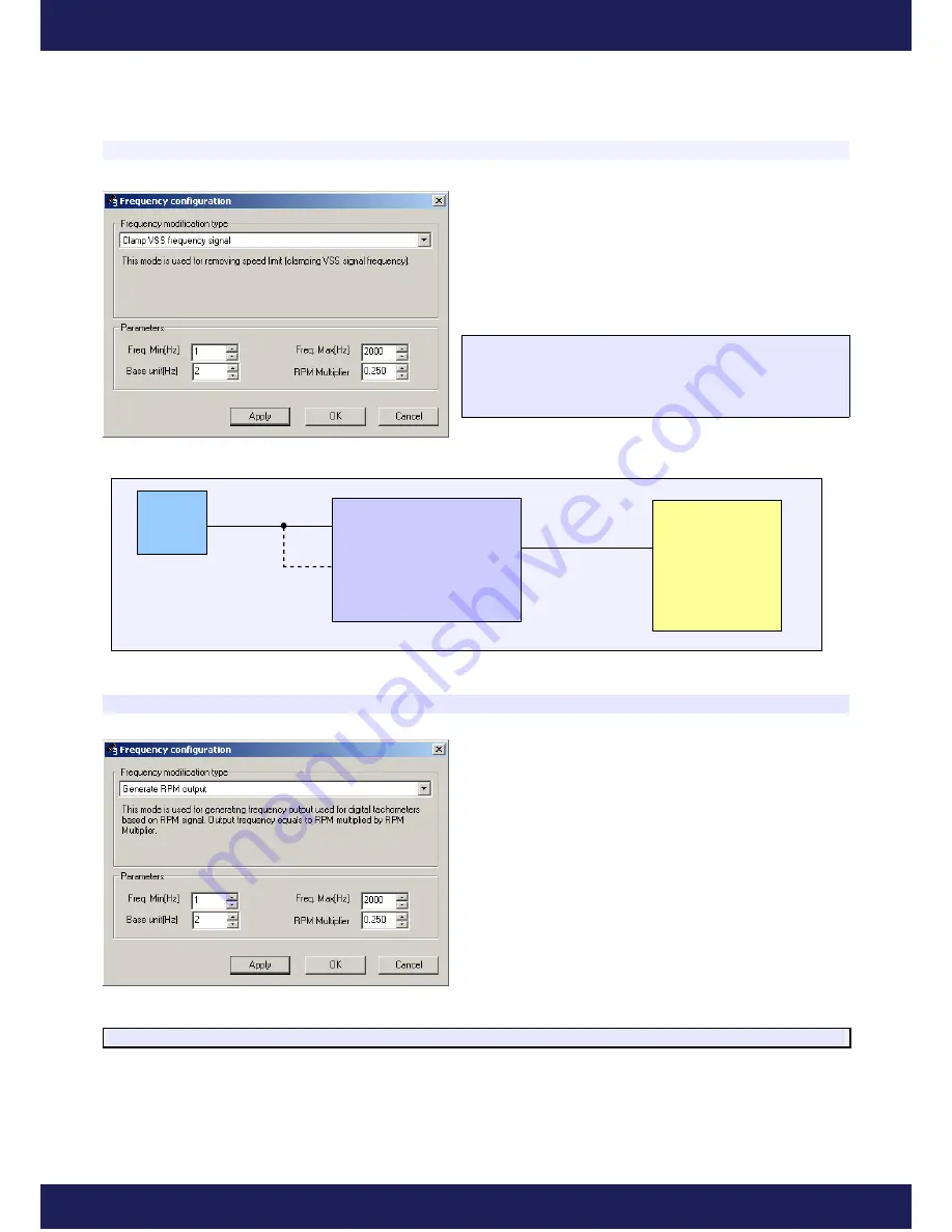
Clamping the upper and lower value of the input frequency.
When “clamping” the frequency signal value is necessary
(for example, removing road speed governor by limiting
frequency of the VSS sensor) it is advised to use “
Clamp
VSS frequency signal
” mode. This mode doesn't require the
Fuel Table, so this table can be used for other purposes.
FreqOut
= FreqIn
If (
FreqOut
< FreqMin)
FreqOut
= FreqMin
If (
FreqOut
> FreqMax)
FreqOut
= FreqMax
An exemplary wiring diagram of the VSS sensor connecting.
4. Generating the output signal for digital tachometers.
It is possible to generate frequency signal for digital
tachometers (where signal is received from ECU and not
from the ignition coil.) Frequency of the output signal
depends on the current engine speed mulitplied by the
RPM
Multiplier
factor, which is used for adjusting the signal to a
specific tachometer.
FreqOut
=
RPM / 60 * RPM_MULTIPLIER
Page 35
www.ecumaster.com
ECU
Frequency In (9)
Frequency Out (7)
Pullup (8)
DET 3
VSS Sensor


