background image

7

INSTALLATION INSTRUCTIONS

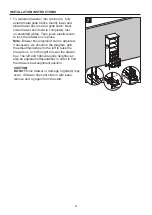
3. Clean area where the cabinet (A) will be 

    permanently located prior to beginning  

    installation, ensuring the cabinet (A) will not 

    interfere with any plumbing or electrical lines 

    once mounted.

    Locate wall studs and mark locations. With the 

    help of another adult, place completed cabinet 

    assembly in its final location. Adjust the height 

    of the cabinet (A) by twisting the adjustable 

    leveler foot pins on the bottom of each leg. 

    Twist clockwise to decrease height or twist 

    counter-clockwise to increase cabinet height. 

    Using hardware appropriate for your wall type 

    such as cabinet screw or toggle bolt (not 

    included), secure cabinet (A) to preferably

    two wall studs anywhere through the cabinet 

    mounting bar. Be careful not to disturb 

    any electrical or water lines that may be 

    concealed in the wall.  

CC

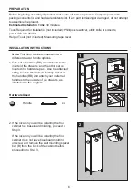
4. Screw shelf pins (CC) hand tight into the threaded 

    holes of cabinet (A). Place shelf (C) on top of shelf 

    pins (CC). 

    Repeat for the remaining shelf (C).

Hardware Used 

Shelf Pin

x 8

Baseboard

3

1

2

A

4

1

CC

2

C

2

C

A

Summary of Contents for 1480FC-24-201

Page 1: ...BATH EDBYELLEN COM...

Page 2: ...y designed high quality products for home pets and people All ED merchandise design and materials are approved by Ellen ensuring it maintains her standards and upholds her promise to make each item fe...

Page 3: ...parts Before returning to your retailer call our customer service department at 1 855 571 1044 9 a m 5 p m EST Monday Friday 1480FC 24 201 24 White Finish Floor Cabinet 1480FC 24 283 24 Coastal Oak Fi...

Page 4: ...4 TABLE OF CONTENTS Package Contents 5 Hardware Contents 5 Safety Instructions 5 Preparation 6 Assembly or Installation Instructions 6 Care and Maintenance 10 Warranty 10 Replacement Parts List 11...

Page 5: ...wrap all parts Make sure you DO NOT discard the hardware Follow these instructions closely take your time and use care while assembling this floor cabinet KEEP THESE INSTRUCTIONS FOR FUTURE REFERENCE...

Page 6: ...4 1 2 3 BB 1 A F F G 2 1 A B 2 2 If the location you will be installing the floor cabinet has baseboard molding proceed to Step 3 If the location you will be installing the floor cabinet does not have...

Page 7: ...foot pins on the bottom of each leg Twist clockwise to decrease height or twist counter clockwise to increase cabinet height Using hardware appropriate for your wall type such as cabinet screw or tog...

Page 8: ...es E flat in the lower drawer G 6 As shown in the diagram fully extend the drawer and locate the plastic levers on the metal glide tracks Push the left side and right side levers at the same time to d...

Page 9: ...box in place Note Drawer box alignment can be adjusted if necessary As shown in the diagram spin the adjustment wheel to the left to raise the drawer box or to the right to lower the drawer box The l...

Page 10: ...a period of one 1 year from the date of original retail purchase This warranty applies only to the original purchaser This warranty does not apply to any damage on the product by accident misuse or mo...

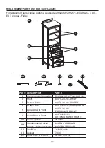
Page 11: ...480FC 24 201 SHELF C Shelf 1480FC 24 201 DRAWER BOX 1480FC 24 201 DIVIDER D Drawer Divider E Drawer Box 1480FC 24 201 TOP DRAWER FRONT H Upper Drawer Front 1480FC 24 201 BOTTOM DRAWER FRONT I Lower Dr...

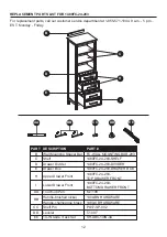
Page 12: ...480FC 24 283 SHELF C Shelf 1480FC 24 283 DRAWER BOX 1480FC 24 283 DIVIDER D Drawer Divider E Drawer Box 1480FC 24 283 TOP DRAWER FRONT H Upper Drawer Front 1480FC 24 283 BOTTOM DRAWER FRONT I Lower Dr...

Page 13: ...WWW EDBYELLEN COM...

Page 14: ......

Reviews: