SIMS GO
56
4.6
Plate Setup Ribbon
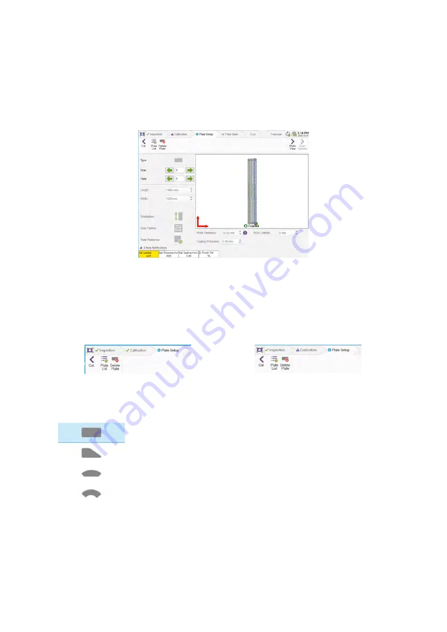
In the plate setup page, a graphical representation of the plate being created is displayed. From this
page the plate list can also be accessed, and the option to delete a created plate is available at the
top of the page.
Once a calibration is loaded, the next step is to open the plate setup page to create plates which
correspond to the plate thickness and coating thickness of the loaded calibration.
Figure 61: Plate setup page
NOTE
If a loaded plate was not scanned using the current loaded calibration, the cal. loaded info-
field displays with a yellow background and the calibration tab in the ribbon displays a purple
exclamation mark. Once the expected calibration is loaded the cal. loaded info-field
background turns to white and a green checkmark displays at the left of the calibration
ribbon.
Figure 62: Green tick on calibration ribbon
Figure 63: Purple exclamation mark on calibration ribbon
Plate Type
The plate’s type can be set to one of these options:
Rectangular.
Sketch.
Annular with straight bottom.
Annular with curved bottom.
Row and Plate Number
The row and plate numbers set the position of the plate relative to the other plates in the tank. The
software uses the row / plate numbering system during the inspection which is taken in relation to
the tank datum. The numbering system begins in the top left-hand corner of the tank with the row
number increases downwards and the plate number increases from left to right and resets on each
Summary of Contents for Floormap X
Page 1: ...User s Manual Floormap X MFL Array Tank Floor Inspection Solution...
Page 10: ...10 Chapter 1 Precautions and conventions...
Page 16: ...General Precautions and Conventions 16 1 5 EU Declaration of Conformity...
Page 19: ...19 Chapter 2 FloormapX System Overview...
Page 35: ...35 Chapter 3 Inspection Preparation Setup and Operation...
Page 43: ...43 Chapter 4 SIMS GO Data Acquisition Software...
Page 69: ...69 Chapter 5 SIMS PRO...


