17
3.
LYNCS
TM
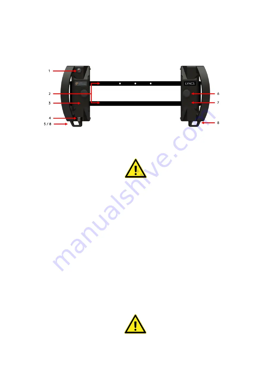
Scanner Frame General Overview
Top View
Figure 9: Scanner frame top overview
1.
On board controls
Depending upon the system hardware
setup the on-board button can be used
during the inspection for either
Pause /
Resume
or
Increment / Encoder Reset
functionality. Refer to LYNCS WI and
LYNCS CM overview for hardware setups.
2.
Scanner frame and end caps
Scanner frame: Consists of two identical
length rails used to mount the tractor
units, tool posts and corrosion mapping
mount.
End caps: Remove the end caps via two
captive thumbscrews to insert / remove
the tractor units, tool posts, corrosion
mapping mount, cable and hose guides,
and other accessories.
3.
Left electronic tractor unit
The left tractor is the electronic unit
assembly which houses the on-board
button controls and the encoder.
4.
Encoder umbilical socket
Connect the encoder cable to this socket
to provide communication back to the
instrument.
5.
Encoder cable strain relief point
Used to provide strain relief on the
encoder cable.
Prior to use, ensure the encoder strain
relief is applied. Failure to do so could
result in encoder cable or tractor unit
damage.
Do not use the encoder strain relief
point to tether the scanner unit.
6.
Tractor unit clamping mechanism
Used to hold the tractor unit in place on
the scanner frame.
Loosen
the
thumbscrew
counter
clockwise to adjust tractor unit position.
Tighten the thumbscrew clockwise to
lock tractor unit in place on the rail.
7.
Right mechanical tractor unit
The right tractor is a mechanical tractor
unit assembly. It contains no electronics.
8.
Umbilical assembly strain relief
points
Used to provide strain relief on the
umbilical cable assembly.
Prior to use, ensure the umbilical strain
relief is correctly applied. Failure to do
so could result in damage to the
assembly.
Do not use the umbilical strain relief
points to tether the scanner.


