background image


Magg™ 480 User Manual 


Document: UMDU011367.docm  

Revision: A06 

Created by: JS 

Date: 13 Apr 2021 

IPN: 3063241-A06 

Source Location: C:\ePDM\ISLEng\Products\DU-MiniMag\Manuals\UMDU011367.docm


Page 26 of 38 


User Ma

nual


Payload Calculations 


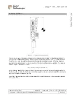
FIGURE 1:  PAYLOAD CALCULATION 

The maximum payload calculation is based on the magnet’s ability to resist the gravitational moment (or 
torque) induced at the driving surface.  When payload weight and/or distance from the wall is increased, 
the vehicle tries to pivot away from the wall and the magnets resist this moment.  When the maximum 
payload moment is exceeded, the vehicle may fall off the driving surface during operation.  The payload 
moment may be calculated as follows: 

𝑀 = 𝑊 × 𝐷 ≤ 5.8 kg · m  (500 lb · in)


Where W is the weight of the payload, and D is the distance of the center of gravity of the payload from 
the driving surface.  Note that the chassis and tether weight has already been accounted for and does not 
have to be included in customer payload. 

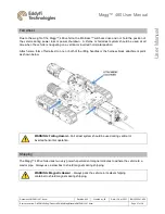
The above calculation is for operation on 

flat surfaces

.  Payload calculations are de-rated for operation 

on curved surfaces.   


Summary of Contents for Magg 480

Page 1: ...Eddyfi Robotics Inc 2569 Kenworth Road Suite C Nanaimo BC V9T 3M4 CANADA 1 250 729 8080 info eddyfitechnologies com www eddyfitechnologies com Magg 480 Magnetic Inspection Crawler...

Page 2: ...Personnel Requirements 11 Working and Storage Environment 11 System Power 12 Power Requirements 12 Set the Line Voltage 12 Generators Inverters 12 Connections 13 Pre Configured Control Rack 13 Control...

Page 3: ...ration 28 Pre Operations Check 28 Post Operations Check 29 ICON Software 29 Power Up Sequence 29 Ground Fault Detection Alarms 30 Driving the Vehicle 31 Inspection Guidelines 31 Powered Winch Operatio...

Page 4: ...Apr 2021 IPN 3063241 A06 Source Location C ePDM ISLEng Products DU MiniMag Manuals UMDU011367 docm Page 4 of 38 User Manual Ordering Parts Customer Service 37 Warranty Repairs 37 Factory Returns to Ca...

Page 5: ...anual Eddyfi Technologies reserves the right to change and or amend these specifications at any time without notice Information in this manual does not necessarily replace specific regulations codes s...

Page 6: ...ased on magnetic adhesion when driving vertically or inverted see Magnet Spacing 3 Maximum payload depends on payload locations see Payload Calculations 4 Actual travel distance may be decreased depen...

Page 7: ...nuals must be also read before using the system WARNING High Voltage The tether carries 400 VDC to the rear harness block and the Minitrac whips carry 400 VDC from the harness block to the tracks Alwa...

Page 8: ...anically weak and magnetically very strong They must therefore be handled very carefully to avoid damage Note To reduce risk of injury and damage to equipment always store the Magg 480 magnetic vehicl...

Page 9: ...e damage may result Although designed for durability the vehicle and its components or attached devices may suffer structural damage if dropped or impacted A lifeline or fall arrest system should be u...

Page 10: ...ving components can draw fingers into a pinch position Do not handle the vehicle while mobile parts are running turn off power or disconnect the tether while reconfiguring or maintaining the vehicle W...

Page 11: ...communication between the operator and deployment personnel Good communication can avoid accidents damage to the equipment and promotes efficiency and productivity In particular the person deploying t...

Page 12: ...the line voltage Monitor Universal no action required Computer Universal no action required Interface Box Universal no action required Power Supply Set the line voltage switch to 115 230VAC and change...

Page 13: ...er Manual Connections Pre Configured Control Rack The monitor computer interface box and power supply are typically installed and connected in a shock mount portable 19 in rack case Systems pre config...

Page 14: ...ree way splitter and the rear monitor or video capture to channel D E or F These are the default output but the connector assignments are also software configurable Control System Connections HD Video...

Page 15: ...er Manual video system and D E or F for rear video There are spare front and rear video outputs which can be connected to external monitors 6 Options for HD video out include HD SDI USB3 internal capt...

Page 16: ...egrated harness block Visually line up the key in the connector before mating Fully screw down and hand tighten the locking collar 2 Secure the tow cable to the cable grip on the tether using the quic...

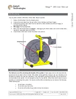
Page 17: ...ack and turn on the locking pin 4 Make sure the friction brake is engaged disengaging the friction brake can result in slack tether resulting in potentially jamming the reel 5 Unwind some tether and c...

Page 18: ...the friction brake can result in slack tether resulting in potentially jamming the reel 6 Unwind some tether and connect the tether to the vehicle Tether Handling The tether is one of the most import...

Page 19: ...prior to engaging Never plug in a dirty or damaged connector Visually align keyways or locating pins prior to engaging the connector Always fully engage or tighten the connector Secure locking collar...

Page 20: ...g 480 User Manual Document UMDU011367 docm Revision A06 Created by JS Date 13 Apr 2021 IPN 3063241 A06 Source Location C ePDM ISLEng Products DU MiniMag Manuals UMDU011367 docm Page 20 of 38 User Manu...

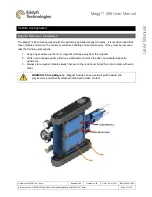
Page 21: ...that these modules remain on the vehicle to minimize handling and potential injury If they must be removed take the following precautions 1 Keep any sensitive electronic or magnetic devices away from...

Page 22: ...its side bracing may be required 2 Cover the top magnet module with foam wood or some other non ferrous material at least 50 mm 2 in thick 3 Remove the 4x M6 x 30 mm FHMS from the bottom magnet module...

Page 23: ...pattern across the four corners Tighten the screws clockwise to increase the height and decrease the magnetic force Loosen the screws counterclockwise to decrease the height and increase the magnetic...

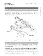
Page 24: ...Pull the tracks free and disconnect the track connectors Installation of the Minitracs is opposite of removal make sure to align mating pins and lubricate the male connector Minitrac Control It is re...

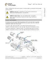
Page 25: ...le The clutch may freewheel causing the vehicle to freely coast down the driving surface Camera Light Installation The vehicle comes standard with a forward facing Spectrum 90 and two 901 lights The S...

Page 26: ...wall is increased the vehicle tries to pivot away from the wall and the magnets resist this moment When the maximum payload moment is exceeded the vehicle may fall off the driving surface during opera...

Page 27: ...sed at all time when the vehicle is navigating on a vertical or inverted horizontal position Attach some form of fall arrest to one or both of the lifting handles or the harness block attachment point...

Page 28: ...anical damage to the chassis or cable harnesses which could affect its operation Ensure that all fasteners are in place and secure In particular check the fasteners holding on cameras lights tracks an...

Page 29: ...ical damage or personal injuries Take time to pack the system properly for transport away from the worksite Store the system in a dry environment Note Ensuring the Magg 480 system is always stored in...

Page 30: ...ent leakage from the high voltage power feed to the tether and vehicle A TETHER fault warning may indicate possible damage to the tether cable or water leakage inside the harness block or Minitracs Th...

Page 31: ...cording of video and other data for review by the customer or pipe owner If a recording is lost fails to record or is of poor quality the inspection will likely have to be re done at the operator s ex...

Page 32: ...but the tether will not reel in the tether is caught on something Try to look for and fix the cause of the catch before putting any more strain on the tether The operator should use any dexterity avai...

Page 33: ...nt breaks in the camera harness cable o Check the tether connectors at both controller and vehicle o Check for tether or slip ring damage by testing tether continuity Picture is blurry will not focus...

Page 34: ...lure the run stop switch must be reset o If there are no lights on the controller check the fuse on the winch and in the motor control box Refer to the winch manual Intermittent problems with vehicle...

Page 35: ...cameras Contact your sales representative for anode replacements Rinsing and Cleaning After every mission check to see if the vehicle needs cleaning 1 If the system has been used in salt water thorou...

Page 36: ...as well as to protect the equipment from damage If a fuse blows stop and look for possible causes Causes might include cable damage water incursion or improper connections See the controller manual fo...

Page 37: ...umber of the system component in question Eddyfi Robotics Inc Canadian Headquarters and Manufacturing Location 2569 Kenworth Road Suite C Nanaimo BC V9T 3M4 CANADA TF 1 877 468 5886 T 1 250 729 8080 i...

Page 38: ...not labelled as per the instructions the items may be held by customs and issued additional fees All returned items must be sent prepaid unless other specific arrangements have been made When the pro...

Reviews: