WARNING
Pinch Hazards & Powerful Manets. The Pipescan system utilises powerful magnets and as such presents an inherent trap
risk. Care must always be taken when handling and using the Pipescan system.
Removal / Deployment jacking handle. Due to the powerful magnets involved, the handle used to deploy and remove the
Pipescan head from the surface can exhibit a strong force and present a finger trap. It is recommended to only use the
black handles on the removal / deployment handle when attempting to remove or deploy the Pipescan.
3
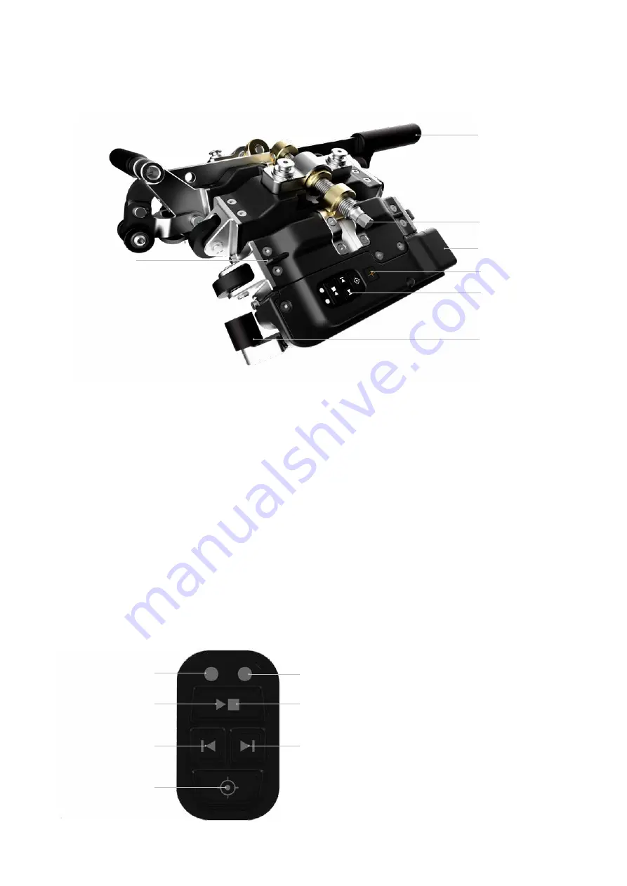
3. PIPESCAN HD OVERVIEW
Pipescan Head
1. Jacking handle, use upon deployment and removal of
the Pipescan Head.
2. Curvature adjustment mechanism, used to adjust the
curvature of Pipescan head to match the inspection
surface outer diameter.
The Pipescan head should be adjusted to nominal OD while
the head is not on the inspection surface. Adjusting the
curvature while on the part could damage the mechanism
due to the strength of the magnets being attracted by the
surface. Final fine-tuning can be done on the inspected
part.
3. Connector for detachable umbilical cable (not to be
used as handle).
4. Label for scan direction and physical zero axial position.
5. Control buttons.
6. Detachable optical encoder.
7. Sensors positions, sensor #1 and #28 are indicated by
the position of the fins on the first and last bridge).
*The top of the C-Scan displayed on the instrument
corresponds to the sensor closer to the electronic module
of the head.
Control Buttons
2. Curvature adjustment
mechanism
1. Jacking handle
6. Encoder
5. Control Buttons
4. Physical zero axial position
7. Sensor position
3. Umbilical connector
Green LED
(Acquisition started)
Start acquistion
Not used
Null
Red LED (Not used)
Stop acquistion
Next pass for raster scan


