9
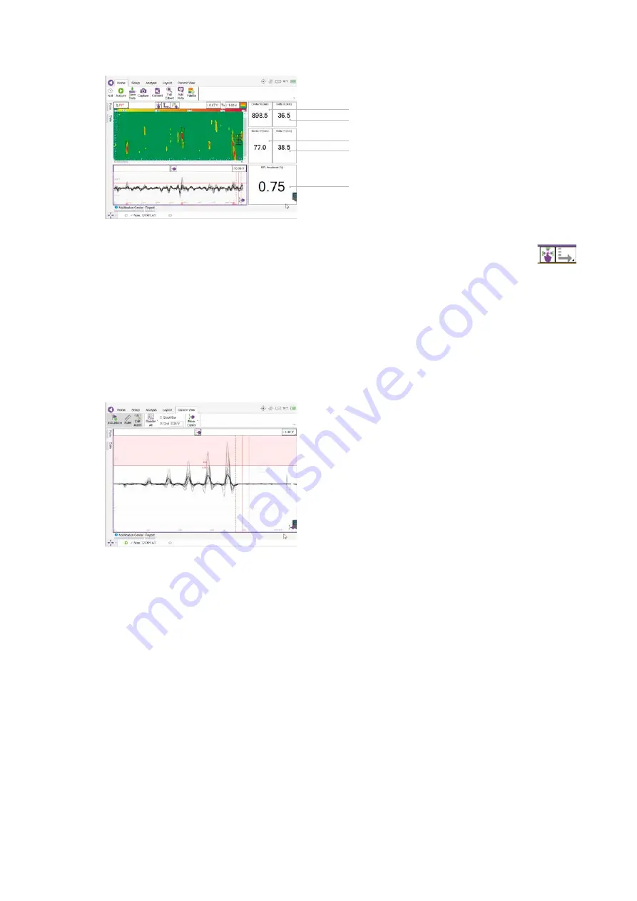
6. The image on the screen should now represent the scanned area.
7. After the first scan there are three main set up requirements.
7.1
Cursor:
Size the cursor to the required size. To change the size of the cursor the user can select either
or use the hardware button capability option on the bottom left hand side of the Screen.
7.2
C-Scan colour palette:
Change the color palette to Filter out unwanted data. To use the colour palette
select the Palette button in the ribbon.
7.3
Strip chart alarm:
There maybe a requirement to set an alarm in the strip chart meaning any indications
above this alarm are automatically ‘tagged’ as indications of interest. To set the alarm.
i Select the strip chart (user will see a purple perimeter around the strip chart viewing pane)
ii Select Current view (last tab available)
iii Select Edit alarm
The user can then move the red alarm line as desired.
8. When these requirements are as desired the system is ready to Acquire inspection data.
current position of the cursors in the C-scan (X-axis)
width of the cursors in the C-scan in the scan (X-axis)
current position of the cursors in the C-scan (Y-axis)
height of the cursors in the C-scan in the index axis (Y-axis)
signal amplitude measured in the MFL C-scan at the cursor position.


