background image


11 

Eder Forestrytools 

310003_04 | 06.2019


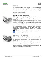
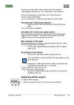
EDER Curved Planer Set ERH-A56 

Field of application: 

For planing round, flat or curved wood surfaces 

up to 30 cm diameter. 

The  design  of  the  cylinder  results  in  high  cutting  performance  with 
minimum effort.   

The  knives  mounted  on  the  rotating  cylinder  are  continuously 
adjustable, allowing you to set both the cutting radius and the cutting 
depth according to the desired chip thickness.  

On the cylinder there are four knives distributed on two levels, which 
produce a smooth surface without vibrations. 

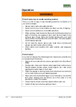
EDER Contour Planer Set EKH-A56 

Field  of  application: 

For  planing  straight  and  wavy  wooden 

surfaces,  e.g.  when  building  log  houses,  children's  playgrounds, 
bonanza fences and similar projects. Well suited for very hard woods 
such as robinia wood. 

The  design  of  the  cylinder  results  in  high  cutting  performance  with 
minimum effort.   

The  adjustable minimum knife  projection setting  effectively  prevents 
the log from splitting. As one rotation of the cylinder means only one 
cut  at  working  width,  the  reaction  forces  are  kept  to  a  minimum. 
Knots and thin branches are easily and cleanly planed off. 

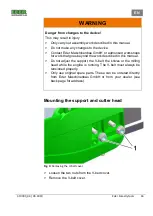
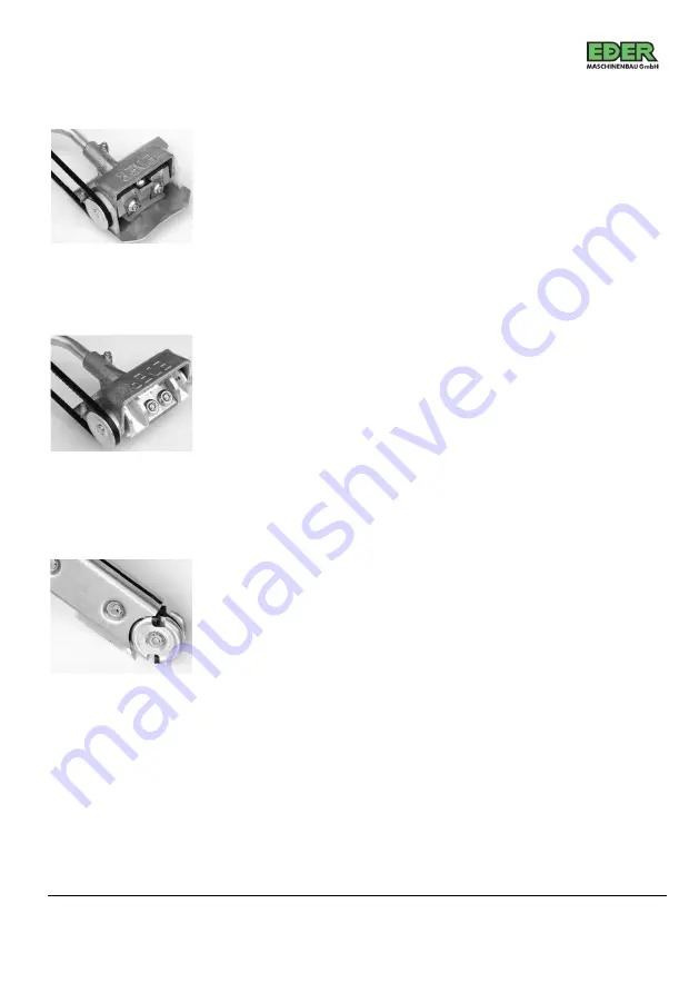
EDER Trough Cutter Set ETH-A56 

Field  of  application: 

For  milling  recesses  in  wooden  surfaces,  for 

making  troughs  and  sculptures,  for  surgical  measures  on  trees  and 
for removing trunk pieces.  

The  design  of  the  milling  head  results  in  high  cutting  performance 
with minimum effort. 

The  circular  knives  are  arranged  so  that  the  tool  can  be  used  for 
performing  work  lengthwise  as  well  as  diagonally.  Two  circular 
knives  are  fitted  on  the  milling  head,  producing  a  smooth  surface 
without  any  vibrations.  The  minimum  knife  projection  setting 
effectively prevents the log from splitting.  


Summary of Contents for EBFH-A56

Page 1: ...Original 310003_04 06 2019 j Operating Instructions EDER Forestrytools Motorised handheld device for working logs and wood EN ...

Page 2: ...Qualification of the personnel 6 Points to observe 7 General safety instructions 7 Safety instructions for the workplace 7 Behaviour in an emergency 8 Safety devices 8 Personal protective equipment 8 Design and function 9 Function 10 Symbols on the drive motor 13 Scope of delivery 13 Transport 14 Assembly 15 Mounting the support and cutter head 16 Mounting the attachment 18 Commissioning and opera...

Page 3: ...e knives 26 Cleaning 35 Maintenance 36 Maintenance schedule 37 Cleaning the air filter 39 Changing the carburettor filter 40 Adjusting the carburettor 40 Replacing the starter cord 42 Replacing the spring 44 Checking the spark plug 44 Checking the starting system 45 Decommissioning and disposal 45 Storage 45 Faults 46 Technical data 48 Accessories and spare parts 49 Declaration of conformity 58 ...

Page 4: ...ust be notified immediately of any defects that can be proven to be due to material or assembly errors Proof of purchase of the attachment set must be provided by presenting the invoice and receipt when making a claim under the warranty The warranty is excluded with regard to the parts if the defects are caused by natural wear and tear temperature weather conditions as well as defects resulting fr...

Page 5: ...efects occurring within the warranty period due to material or manufacturing faults must be remedied by repair if they have occurred despite proper operation and care of the machine Presentation of the warning notes SIGNAL WORD Type and source of the danger Consequences Danger prevention The warning sign warning triangle draws attention to danger of life or injury The signal word indicates the sev...

Page 6: ... Symbol Meaning If this information is not observed this can lead to deterioration in the operating process Instruction for action Describes actions that must be carried out Safety instructions The motorised handheld device has been manufactured in accordance with the generally recognized rules of technology Nevertheless there is a risk of personal injury and damage to property if you do not obser...

Page 7: ...e chapter Intended use using the motorised handheld device under operating conditions that differ from those described in this manual If the device is not used as intended all warranty claims will become void The manufacturer is not liable for damage to the device and for personal injury resulting from improper use Qualification of the personnel The motorised handheld device may only be operated m...

Page 8: ...ructions for the workplace Ensure that the workplace and the traffic routes required for transporting the wood to and from the site are safe Keep the working area free of wood debris obstacles and tripping hazards Eliminate slippery and smooth areas Do not use sawdust or wood ash for this purpose otherwise there is a risk of slipping Ensure adequate lighting at the workplace Ensure that a level an...

Page 9: ...d with the protective and safety equipment e g protective plate provided for the intended use Protective and safety equipment must never be disabled and must be cleaned if necessary Personal protective equipment Always wear the following personal protective equipment when operating the machine Safety shoes with steel toecap Cut resistant pants and tight fitting clothes Suitable work gloves Safety ...

Page 10: ... 2 Front handle 11 Engine starter handle 3 Air filter cover 12 Fuel filler cap 4 Primer 13 Stop switch Position A Cold start Position B Operation Position C Stop 5 Throttle handle 14 Throttle trigger 6 Rear hand guard 15 Throttle trigger lockout lever 7 V belt cover 16 Throttle lock 8 V belt brake 17 Air filter cover 9 Clutch bell 18 Pressure relief valve ...

Page 11: ...he bark thickness over the entire length of the log Knots and thin branches are easily and cleanly milled off The cylinder is straight and mills a flat surface similar to that of the peeling knife This allows you to use the device at an angle or crosswise when working on the side of the trunk and when peeling root knots For the processing of robinia wood we recommend the use of the contour planer ...

Page 12: ...hard woods such as robinia wood The design of the cylinder results in high cutting performance with minimum effort The adjustable minimum knife projection setting effectively prevents the log from splitting As one rotation of the cylinder means only one cut at working width the reaction forces are kept to a minimum Knots and thin branches are easily and cleanly planed off EDER Trough Cutter Set ET...

Page 13: ...el or iron and for removing rust or old paint The EDER Wire Brush ERB is exceptionally suitable for working out the natural structure of the wood grain on boards beams and round timber e g during construction restoration and maintenance work on log houses children s playgrounds park benches wooden fences on weathered and rotten wood and similar projects EDER Bark Beetle Cutter Set EBF A56 Field of...

Page 14: ...nch and slotted screwdriver Allen key 6 mm 5 mm and 4 mm Phillips screwdriver 1x setting gauge ESG A56 EPH A56 ERH A56 EKH A56 ESF A56 Fig 2 Symbols on the drive motor 1 Company address 7 Only two hand operation permitted 2 Serial number 8 One handed operation prohibited 3 Wear eye and hearing protection 9 Caution Inflammable 4 Wear work gloves 10 Caution Hot surface 5 Wear safety shoes 11 CE mark...

Page 15: ...nsurer If you suspect latent transport damage Report concealed transport damage within two days at the latest which means that you must have checked your delivered goods within this period Reporting damage after this time is usually not accepted Make a note on the shipping documents in any case Goods are accepted subject to concealed transport damage Insurance companies of carriers often react ver...

Page 16: ...onsists of a drive motor and an attachment You can transport the motorised handheld device assembled or the parts separately A handle is attached to the upper part of the drive motor The motorised handheld device weighs approx 8 9 kg depending on the attachment used Carry the motorised handheld device by the front handle 1 to the work site Assembly WARNING Danger during assembly with the drive mot...

Page 17: ...ork that goes beyond the work described in this manual Do not adjust the support the V belt the knives or the milling head while the engine is running The V belt must always be tensioned properly Only use original spare parts These can be ordered directly from Eder Maschinenbau GmbH or from your dealer see back page for address Mounting the support and cutter head Fig 3 Removing the V belt cover L...

Page 18: ...ch drum Fig 5 Fastening the peeling head to the support Make sure that the belt is already slightly pretensioned If not loosen the Allen screw 1 see Fig 5 and push the peeling head forward on the support until the belt is pretensioned Replace the V belt cover so that the pin in the cover 3 engages in the support 1 see Fig 4 Tighten the V belt by turning the V belt tightening screw 2 clockwise see ...

Page 19: ...tween the clutch drum 5 Fig 3 and the V belt pulley 1 Fig 4 Commissioning and operation ATTENTION Damage to knives and tools Nails adhering sand and other foreign bodies can damage the knives and tools of the attachment Check the logs to be worked before each use If necessary remove nails sand and other foreign objects before milling Before starting the motorised handheld device make sure you have...

Page 20: ...NG Danger to life from open fire The petrol mixture can ignite by open fire Never smoke while refuelling the device Keep the device away from naked flames Always switch off the engine before refuelling and wait at least 5 minutes for the engine to cool down ATTENTION Damage to the engine due to incorrect fuel The device is equipped with a 2 stroke engine and may therefore only be operated with an ...

Page 21: ...mogeneous Before refuelling carefully clean the area around the fuel filler cap to prevent dirt from entering the tank and damaging the engine Slowly unscrew the tank cap to release any excess pressure Fill the mixture into the tank Fill the tank only to allow the mixture to expand After refuelling correctly refasten the tank cap Remove the motorised handheld device at least 3 meters from the fuel...

Page 22: ...lt brake before starting work see Preparing to start the device Place the motorised handheld device on the ground so that the device does not touch any foreign objects Never start the device in a hanging position Keep the device away from your body during work Make sure that no one is in the working area of the device Preparing to start the device Fig 7 Starting the drive motor ...

Page 23: ...aged Press the primer 4 5 or 6 times Starting the engine Insert your foot into the throttle handle p 8 Fig 1 no 5 Pull the engine starter handle Fig 7 no 7 slowly until you feel a little resistance Now pull the engine starter handle quickly and firmly Relax the cable and allow it to be rewound in a controlled manner by continuing to hold the engine starter handle in your hand Continue doing this u...

Page 24: ...subject to wear Have the V belt brake checked regularly by qualified personnel to ensure the safety of the operator Have a damaged braking device repaired immediately by qualified personnel If you engage the V belt brake frequently at high speed the braking device may be damaged Engage the V belt brake at full throttle only if there is an emergency You may use the V belt brake in the following cas...

Page 25: ...also triggered when the operator s hand is not behind the hand guard Releasing the V belt brake Before accelerating or working except during the function check you must release the V belt brake Pull the hand guard backwards towards the front handle see Fig 8 Checking the V belt brake Check the V belt brake before starting any work The V belt brake is only functional if the hand guard has not been ...

Page 26: ...ice above your head when working and always use both hands when working Work calmly and carefully with good visibility and adequate lighting Risk of injury If you do not observe the following points injuries are possible due to rebounding of the device Only work on wood with the device except for the Wire Brush ERB During work make sure that the cutter head does not touch any foreign objects stone...

Page 27: ...urettor performance by mixing the cold air with the warm air from the cylinder To do this open the rotating cover under the air filter Switch off the engine Remove the air filter cover 1 and the air filter Loosen the screw and turn the rotating cover 2 until the opening is free Retighten the screw The intake air is now preheated Changing and adjusting the knives EDER Bark Stripper Set ESG A56 Shar...

Page 28: ...as follows for each knife Loosen the Allen screw of the knife with a 6 mm Allen key Replace the knife if necessary Push the setting gauge 2 under the knife in the direction of the arrow up to the peeling cylinder 1 Push the knife back or forward until the cutting edge touches the zero mark If the device cuts too deeply or even chops Move the knife in negative direction If the cutting depth is too ...

Page 29: ...e is 40 Fig 10 Allen wrench with notches To adjust the knives you need the 6 mm Allen key This key has notches for three settings of the knives 0 4 mm 0 7 mm and 1 mm The required knife setting depends on the type of wood to be peeled Adjust the knives from case to case The smaller the knife protrusion the less wood is removed and the smoother the surface becomes All knives are changed and adjuste...

Page 30: ... knife Move the knife so that the cutting edge touches the Allen key at the point with the desired cutting depth Retighten the Allen screw of the knife Tightening torque 35 Nm EDER Contour Planer Set EKH A56 Sharp knives are required for optimal work with the EDER Contour Planer Set EKH A56 Blunt knives can be sharpened manually using normal grinding wheels Cutting edge angle is 40 For adjustment ...

Page 31: ...linder at the top and bottom Push the knife onto the knife gauge until the desired setting height 0 2 mm 0 4 mm 0 6 mm is reached Retighten the knife screw Tightening torque 35 Nm EDER Trough Cutter Set ETH A56 Sharp knives are required for optimal work with the EDER Trough Cutter Set ETH A56 Blunt circular knives can be turned by 180 around the knife screw and used again The circular knives can b...

Page 32: ...by 180 Retighten the knife screw Tightening torque 35 Nm Setting the guide block on the EDER Trough Cutter Set ETH A56 The position of the guide block determines the depth of the cavities Clamp the tip of the guide block on the lower side between the protective plates Slide the guide block between the protective plates in longitudinal direction as required For deep cavities move it far forward For...

Page 33: ...ng Cutter Set ESF A56 Sharp knives are required for optimal work with the EDER Carving Cutter Set ESF A56 Blunt knives can be sharpened manually using normal grinding wheels Cutting edge angle is 40 The rounding radius of the knives must be maintained otherwise the knives will carve unevenly For adjustment you need the supplied knife gauge Both knives are adjusted in the same way The knives must n...

Page 34: ...he knife gauge 4 Fig 12 on the milling head 1 Fig 12 and slide the knife 3 Fig 12 against the gauge until it touches the notched area Fix the knife in this position by slightly tightening the knife screw Retighten the knife screw Tightening torque 35 Nm EDER Wire Brush Set ERB A56 Changing the wire brush Fig 17 Changing the wire brush ...

Page 35: ...ack on Put the V belt back EDER Bark Beetle Cutter Set EBF A56 Sharp knives are required for optimal work with the EDER Bark Beetle Cutter Set EBF A56 Blunt knives can be sharpened manually using normal grinding wheels Replacing knives Take the V belt off Unscrew the V belt pulley 1 Use pointed pliers and insert them in the side holes of the V belt pulley Unscrew the short bearing shaft 3 and the ...

Page 36: ...ng work switch off the drive motor and secure the device against being switched on again To work safely you must clean the device after each use Remove all wood debris chips and other dirt Use a dry or slightly damp cloth and if necessary a commercially available cleaning agent for the exterior surfaces Do not use any grease dissolving caustic or aggressive cleaning agents If the V belt is dirty C...

Page 37: ...ry out the maintenance and repair work described in this manual Do not make any changes to the device Contact Eder Maschinenbau GmbH or authorised workshops for work that goes beyond the work described in this manual Do not adjust the support the V belt the knives or the milling head while the motor is running The V belt must always be tensioned properly Only use original spare parts These can be ...

Page 38: ...g area longer daily working hours Extension of the intervals Only in the case of occasional use Component Action Before or after end of work After each tank filling Once a week Once a month Once a year In case of malfunction In case of damage If required After 100 operating hours Complete machine Visual inspection x x Clean x Throttle trigger throttle trigger lockout lever stop switch Functional t...

Page 39: ...damage If required After 100 operating hours V belt brake Functional test x x Inspection by specialist dealer x1 Fuel tank Clean x Belt Check whether there is also wear x x Belt tension x x x Air filter Clean x x Replace x Cooling air suction slots Clean x Cylinder ribs Clean x x Carburettor Check idle speed Belt must not run x Adjust idle speed x Spark plug Readjust electrode gap x ...

Page 40: ...asional use once a year Cleaning the air filter Fig 19 Cleaning the air filter If you remove the air filter cover you have access to the air filter see Fig 19 Set the stop switch 4 to the stop position 0 Unscrew the ball handle 1 and remove the air filter cover Unscrew the nuts 3 and remove the air filter 2 Replace x Clean x Accessible screws except adjusting screws Tighten x ...

Page 41: ...r in good working order you must change the carburettor filter 1 once a year Empty the tank Remove the carburettor filter 1 from the tank using a hook or long nose pliers Adjusting the carburettor The carburettor was adjusted at the factory Before adjusting the carburettor check that the air filters are clean Otherwise you will not be able to adjust the carburettor correctly ATTENTION Damage to th...

Page 42: ...a single D screwdriver a device for measuring the rotational speed Carburettor adjustment at minimum Start the engine and let it run for a few minutes Use the single D screwdriver and with the engine running idle turn the adjusting screw L slowly counter clockwise to set the engine to the lowest speed If the engine dies off turn the adjusting screw L slightly back and start again ...

Page 43: ...um Start the engine and let it run for a few minutes Bring the engine up to full speed a few times Make sure that the V belt is moving Accelerate the engine to full throttle and turn the adjusting screw H with the single D screwdriver until a speed between 12 000 and 13 000 rpm is reached Replacing the starter cord Fig 22 Screws on the blower housing Remove the four fixing screws 1 and the blower ...

Page 44: ...ine starter handle 6 and then make a knot as shown in the figure Insert the starter cord into the notch in the washer 3 and turn it 7 turns clockwise Loosen the starter cord slowly The starter cord is wound all the way around the pulley with the help of the previously wound spring Check that the spring is sufficiently wound The engine starter handle must be well tightened If the engine starter han...

Page 45: ...e the spring and insert it in its seat with its spring guard 7 and washer 3 Checking the spark plug The distance between the electrodes of the spark plug must be 0 5 mm To keep the drive motor in good working order you must clean and check the spark plug at least once a week The spark plugs of 2 stroke engines have a relatively short service life They must be changed once a month if used daily Use...

Page 46: ...rized dealer Decommissioning and disposal If the device is no longer fit for use and is to be scrapped you must deactivate and dismantle it i e you must bring the device into a state in which it can no longer be used for the purposes for which it was designed To deactivate the device proceed as follows Empty the fuel tank and run the engine until there is no more fuel When you dispose of the devic...

Page 47: ... Faults If you cannot repair the device yourself contact your dealer or an authorized repair shop Before contacting your dealer an authorized repair shop or the manufacturer please make a note of the data and the machine number on the nameplate This information is required when solving problems or ordering spare parts The nameplate is located on the top of the drive motor The following table lists...

Page 48: ...pport and tighten the Allen screw see Assembly on page 18 Wrong cutting depth poor surface Knives incorrectly adjusted Re adjust the knives Blunt knives Resharpen replace the knives Engine splutters dies off or smokes Incorrect fuel mixture Empty tank and use new mixture Air filter clogged Clean replace air filter Carburettor incorrectly adjusted Re adjust carburettor Motor does not start Spark pl...

Page 49: ...2 8 4 8 8 8 7 8 8 7 8 7 8 8 3 Number of knives 4 4 6 4 4 2 4 Working width mm 120 120 120 120 100 90 30 54 V belt drive ratio XPZ987 SPZ1024 Cubic capacity cm 55 05 Power kW PS 3 0 4 1 Minimum speed 2 800 rpm Permissible maximum speed 13 000 rpm Carburettor Walbro diaphragm carburettor digital primer Switching digital Oil fuel mixture tank capacity 0 65 l Sound pressure level LpA av EN608 ISO7182 ...

Page 50: ...er to persons Damage to the motorised handheld device Malfunctions of the motorized handheld device Failure of the motorised handheld device Only use original spare parts accessories and consumables Only use technically perfect accessories and original spare parts Drive motor Order no Description 310122 Air filter 310121 Spark plug Other spare parts are available on request from your dealer i ...

Page 51: ...llen wrench 03 020301 Cylinder 13 021300 Short bearing bolt 04 020400 V belt pulley 14 021400 Long bearing bolt 05 020500 Protective plate 15 021500 Deep groove ball bearing 2 x 06 310006Z Clutch drum 16 021600 Sealing ring 2 x 07 020700 Clamping screw 17 021700 Circlip 2 x 08 020800 V belt 18 021800 Protective plate fixing screw 6 x 09 020900 Knife 4 x 19 021900 Setting gauge 10 021000 Knife disc...

Page 52: ...14 021400 Long bearing bolt 04 020400 V belt pulley 15 021500 Deep groove ball bearing 2 x 05 020500 Protective plate 16 021600 Sealing ring 2 x 06 310006Z Clutch drum 17 021700 Circlip 2 x 07 020700 Clamping screw 18 021800 Protective plate fixing screw 6 x 08 020800 V belt 19 061900 Guide plate 09 020900 Knife 4 x 20 060600 Mounting screw 8 x 10 061400 Knife disc 4x 21 060700 Guide plate suspens...

Page 53: ... 021400 Long bearing bolt 04 020400 V belt pulley 15 021500 Deep groove ball bearing 2 x 05 020500 Protective plate 16 021600 Sealing ring 2 x 06 310006Z Clutch drum 17 021700 Circlip 2 x 07 020700 Clamping screw 18 021800 Protective plate fixing screw 6 x 08 020800 V belt SPZ 987 19 071900 Guide plate 09 020900 Knife 6 x 20 060600 Mounting screw 8 x 10 061400 Knife disc 6 x 21 070700 Guide plate ...

Page 54: ...0 Allen wrench 03 190300 Cylinder 13 021300 Short bearing bolt 04 020400 V belt pulley 14 021400 Long bearing bolt 05 020500 Protective plate 15 021500 Deep groove ball bearing 2 x 06 310006Z Clutch drum 16 021600 Sealing ring 2 x 07 020700 Clamping screw 17 021700 Circlip 2 x 08 020800 V belt 18 021800 Protective plate fixing screw 6 x 09 020900 Knife 4 x 19 191900 Knife gauge 10 061400 Knife dis...

Page 55: ...ing head 12 021700 Circlip 03 021200 Allen wrench 13 031300 Support disc 04 370002 Base 14 031400 Shaft nut 6 x 05 030500 Bearing shaft 3 x 15 031500 Locking plate 6x 06 030600 Spacer bushes 4 x 16 031600 Feather key 2 x 07 030700 Right protective plate 17 031700 Circular knife 4 x 08 030800 Left protective plate 18 031800 Knife screw 4 x 09 0206xx Clutch drum 19 141900 Guide block with tip 10 370...

Page 56: ...Protective plate 11 021500 Deep groove ball bearing 2 x 03 310006Z Clutch drum 12 021700 Circlip 2 x 04 360001 Base 13 031300 Support disc 2 x 05 130500 Bearing shaft 14 031400 Shaft nut 06 130600 Protective plate fixing screw 2 x 15 031500 Locking plate 07 130700 Washer 2 x 16 021100 Knife screw 2 x 08 061400 Knife disc 2 x 17 131700 Knife gauge 09 130900 Knife 2 x 18 021200 Allen wrench ...

Page 57: ... groove ball bearing 2 x 03 150500 Wire brush 13 021600 Sealing ring 2 x 04 020400 V belt pulley 14 021700 Circlip 2 x 05 020500 Protective plate 15 021800 Protective plate fixing screw 6 x 06 310006Z Clutch drum 16 150400 Locking plate 2 x 07 020700 Clamping screw 17 150800 Shaft nut 2 x 08 020800 V belt 18 150700 Groove nut wrench 2 x 09 021200 Allen wrench 19 150600 Shaft 10 021300 Short bearin...

Page 58: ...roove ball bearing 2 x 04 020400 V belt pulley 16 021600 Sealing ring 2 x 05 020500 Protective plate 17 021700 Circlip 2 x 06 310006Z Clutch drum 18 021800 Protective plate fixing screw 6 x 07 020700 Clamping screw 19 091500 Inner knife 2 x 08 020800 V belt 20 092000 Feather key 2 x 09 091400 Spacer washer 2 x 21 301200 Locking plate 2 x 10 091900 Outer knife 2 x 22 301300 Shaft nut 2 x 11 090600 ...

Page 59: ...H A56 Type ERH A56 Type EKH A56 Type ERB A56 Type ETH A56 Type ESF A56 Type EBF A56 Serial number FT31 001000 and following The following standards were used to implement the safety and health requirements specified in the EC directives 1 EN ISO 12100 Safety of machinery General principles for design risk assessment and risk reduction 2 Centrifugal force test according to DIN EN 847 1 Machine tool...

Page 60: ...Eder Maschinenbau GmbH Schweigerstraße 6 38302 Wolfenbüttel Germany www eder maschinenbau de info eder maschinenbau de ...

Reviews: