background image

15

5. Commissioning

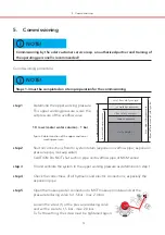
step 6

Switch on power supply and check if the red control lamp beside the key ”0”
glows. If not, deactivate the device by pressing the key ”0” and following
confirmation by pressing the key ”F1” (red control lamp beside the key ”0”
must glow!)

step 7

Fill and ventilate the pressure maintenance pump(s) and the piping.

- The Shut off devices at the intake side of the pump(s) must be opened com-

pletely and the regulating valve at the pumps outlet side must be closed
completely.

- Open the ventilating valve at the pump(s)

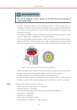
figure : ventilation valve at the pump

4

- If a

makeup module is installed, go to manual mode (user level 3), see

MCF

instruction manual

,

-_1, chapter 5.7, ”user level 3”.

MCK  MCM

- Switch on the output ”makeup valve Y1” (”output: on”) and fill the vessel until

a continuous water jet leaks from the ventilation valve at the pressure mainte-
nance pump. After this set the output ”makeup valve Y1” to automatic mode
(”output: auto”).

figure : ventilation of the pressure maintenance pump(s)

5

Detail A

SW 9

Detail A

B

A

Summary of Contents for MCM Series

Page 1: ...1 ANTON EDER GMBH Weyerstraße 350 A 5733 Bramberg www eder heizung at Ver 10 2019 en Supplement to instruction manual _1 MCK MCM Instruction manual MULTICONTROL M M C _2 _9 ...

Page 2: ...multicontrol device i INFORMATION This document refers to multicontrol series devices with software version V1 26 Design and operation can vary slightly due to the existing software version i Table of contents Disclaimer We improve our products permanently and so we reserve the right to make modifications anytime and without previous announcements We do not assume any guarantee for the correctness...

Page 3: ...ty for rebuilding to the right side of the control unit Temperature monitoring of the media streaming into the vessel Prepared connection point for mounting a makeup module for litre accurate measuring Combinable with water softening for standardized makeup water Prepared connection point for mounting a degassing module for automatic and economic low pressure degassing based on the principle of pr...

Page 4: ...ax temperature of 70 C MCM at the connection point If the max temperature at the connection point exceeds 70 C EV cooling vessels must be installed The implementation into the system return must be done at a position where no external pressure can occur External pressures could affect the trouble free operation of the pressure maintenance device NOTE For detailled information about hydraulic conne...

Page 5: ... aaaaaaaaaaaaaaaaaaaaaaaaaaaaaaaaaaa aaaaaaaaaaaaaaaaaaaaaaaaaaaaaaaaaaa aaaaaaaaaaaaaaaaaaaaaaaaaaaaaaaaaaa aaaaaaaaaaaaaaaaaaaaaaaaaaaaaaaaaaa aaaaaaaaaaaaaaaaaaaaaaaaaaaaaaaaaaa aaaaaaaaaaaaaaaaaaaaaaaaaaaaaaaaaaa aaaaaaaaaaaaaaaaaaaaaaaaaaaaaaaaaaa aaaaaaaaaaaaaaaaaaaaaaaaaaaaaaaaaaa aaaaaaaaaaaaaaaaaaaaaaaaaaaaaaaaaaa aaaaaaaaaaaaaaaaaaaaaaaaaaaaaaaaaaa aaaaaaaaaaaaaaaaaaaaaaaaaaaaaaaaaaa aaa...

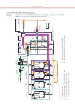
Page 6: ...Z M degassing module makeup module water treatment sensor T2 MAE MCF 1 makeup water 7 gas side vessel connection 20 DN 4 discharge hopper for vessel safety valve expansion pipe from to system return 8 5 suction pipe from expansion vessel degassing pipe from system return 9 6 overflow pipe from expansion vessel 3 Hydraulic diagrams ...

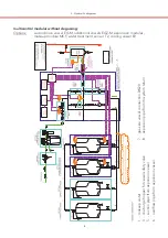
Page 7: ...nsion modules EG EGZ M makeup module water treatment sensor T2 MCF 3 Hydraulic diagrams 1 makeup water 7 gas side vessel connection 20 DN 4 discharge hopper for vessel safety valve expansion pipe from to system return 8 5 suction pipe from expansion vessel 6 overflow pipe from expansion vessel ...

Page 8: ...on pipe from to system return 8 5 suction pipe from expansion vessel 6 overflow pipe from expansion vessel multicontrol without degassing modular Options second main vessel M additional vessels expansion modules EG EGZ M makeup module water treatment sensor T2 cooling vessel MCF EV 3 Hydraulic diagrams ...

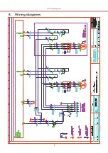
Page 9: ...9 4 Wiring diagrams 4 Wiring diagrams ...

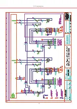
Page 10: ...10 4 Wiring diagrams ...

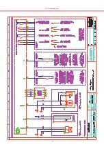
Page 11: ...11 4 Wiring diagrams ...

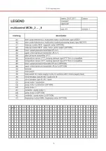
Page 12: ...12 4 Wiring diagrams ...

Page 13: ...aaaaaaaaaaaaaaaaaa aaaaaaaaaaaaaaaaaaaaaaaaaaaaaaaaaaa aaaaaaaaaaaaaaaaaaaaaaaaaaaaaaaaaaa aaaaaaaaaaaaaaaaaaaaaaaaaaaaaaaaaaa aaaaaaaaaaaaaaaaaaaaaaaaaaaaaaaaaaa aaaaaaaaaaaaaaaaaaaaaaaaaaaaaaaaaaa aaaaaaaaaaaaaaaaaaaaaaaaaaaaaaaaaaa aaaaaaaaaaaaaaaaaaaaaaaaaaaaaaaaaaa aaaaaaaaaaaaaaaaaaaaaaaaaaaaaaaaaaa aaaaaaaaaaaaaaaaaaaaaaaaaaaaaaaaaaa notes ...

Page 14: ... and electric connections especially the expansion pipe step 5 Open the makeup water connection to makeup module and set the MCF pressure reducing valve to 1 5 bar max 2 0 bar Loosen the screw 1 at the pressure reducing valve and set the scale to 1 5 bar max 2 0 bar To fix the setting the screw must be tightened again NOTE Steps 1 3 must be completed on site in preparation for the commissioning i ...

Page 15: ...ely and the regulating valve at the pumps outlet side must be closed completely Open the ventilating valve at the pump s figure ventilation valve at the pump 4 If a makeup module is installed go to manual mode user level 3 see MCF instruction manual _1 chapter 5 7 user level 3 MCK MCM Switch on the output makeup valve Y1 output on and fill the vessel until a continuous water jet leaks from the ven...

Page 16: ...hecking the direction of rotation of the pump motor If the fan wheel doesn t rotate in the right direction you have to change 2 of the 3 phases to weaken the rotating field and the direction of the rotation Close the ventilation valve of the pressure maintenance pump At devices with 2 pressure maintenance pumps system Duo and Maxi repeat the above steps for the second pump pump 1 left side pump 2 ...

Page 17: ...owledgement only if module is installed not available default setting is available analog signalling only if module is installed not available default setting is available temperature sensor T2 not available default setting is available level measurement L2 not available default setting is available correction value 2o PL acc to the sticker at the upper pressure transmitter only displayed if level...

Page 18: ...ump stop the overflow valve doesn t close completely before approx 0 5 bar under the upper working pressure The setting 1 of the regulating valve s must be notated at the plant resp commissioning record 1 _________ setting regulating valve pump 2 _________ setting regulating valve pump 1 INFORMATION If device setup was completed successfully only mandatory inputs necessary this menu item is remove...

Page 19: ...sioning The setting of the setpoint at the overflow valve via a black hand wheel b hexagonal nut at the spring cap c set point adjustment depends on the used type of the overflow valve Do not confirm the set upper wor king pressure until the desired pressure is not stable for a few minutes confirm with F1 apply Enter the hysteresis default value 0 5 bar Difference between the set upper working pre...

Page 20: ...utput on Wait until the motor valve opened completely ca 35 sec the scale resp the red axis at the electric actuator must not rotate anymore Open the ball valve at the intake side Open the regulating valve slowly until you hear a flow ca 1 4 turn The plant pressure decreases the pressure maintenance pump starts Look for the plant pressure shown at the display The regulating valve is set correctly ...

Page 21: ...a aaaaaaaaaaaaaaaaaaaaaaaaaaaaaaaaaaa aaaaaaaaaaaaaaaaaaaaaaaaaaaaaaaaaaa aaaaaaaaaaaaaaaaaaaaaaaaaaaaaaaaaaa aaaaaaaaaaaaaaaaaaaaaaaaaaaaaaaaaaa aaaaaaaaaaaaaaaaaaaaaaaaaaaaaaaaaaa aaaaaaaaaaaaaaaaaaaaaaaaaaaaaaaaaaa aaaaaaaaaaaaaaaaaaaaaaaaaaaaaaaaaaa aaaaaaaaaaaaaaaaaaaaaaaaaaaaaaaaaaa aaaaaaaaaaaaaaaaaaaaaaaaaaaaaaaaaaa aaaaaaaaaaaaaaaaaaaaaaaaaaaaaaaaaaa aaaaaaaaaaaaaaaaaaaaaaaaaaaaaaaaaaa aa...

Page 22: ...device PN bar 10 25 16 C voltage V Hz 1x 230 V max electrical power kW 0 6 0 6 0 8 1 3 fuse protection A 10 10 connections 1 Rp1 2 2 Rp1 3 Rp1 5 Rp1 6 Rp1 R6 4 R1 R6 4 R1 R6 4 8 9 elko mat eder multicontrol 1 7 2 4 4 2 modular solo max upper working pressure 16 max temperature at plant connect 70 3x 400 V 50 Hz 10 16 Rp1 2 bzw Rp3 4 R1 R5 4 R1 Rp1 Rp6 4 Rp1 2 technical changes reserved 1 make up m...

Page 23: ... 1 2 0 6 0 4 0 7 8 2 0 6 0 4 0 7 8 4 0 10 0 4 0 10 0 2 4 6 2 2 4 6 2 2 4 6 2 2 4 6 2 2 4 6 6 4 0 10 0 2 4 6 6 4 0 10 0 2 4 6 6 2 4 6 6 8 0 16 0 8 0 16 0 2 4 6 6 6 0 11 0 2 4 6 6 6 0 11 0 nominal pressure device PN bar C voltage V Hz max electrical power kW 1 1 1 1 1 5 1 1 1 1 1 5 fuse protection A connections 1 2 3 5 6 8 9 13 Rp1 2 Rp1 Rp1 Rp1 Rp1 technical changes reserved 1 make up module 2 expa...

Page 24: ... 0 6 6 6 0 8 1 2 4 6 6 6 0 7 8 2 4 6 6 6 0 7 8 6 0 10 4 6 0 10 4 2 4 6 2 2 4 6 2 2 4 6 2 2 4 6 2 2 4 6 6 6 0 10 1 2 4 6 6 6 0 10 1 2 4 6 6 2 4 6 6 8 0 16 0 8 0 16 0 2 4 6 6 6 0 11 0 2 4 6 6 6 0 11 0 nominal pressure device PN bar C voltage V Hz max electrical power kW 1 1 1 1 1 5 1 5 1 1 1 1 1 5 1 5 fuse protection A connections 1 2 3 5 6 8 9 13 Rp1 2 Rp1 Rp1 Rp1 Rp1 Rp1 2 1 make up module 2 expan...

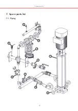
Page 25: ...25 7 Spare parts list 7 1 Piping 1 3 2 4 5 6 7 8 9 10 7 Spare parts list ...

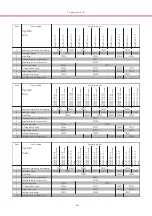
Page 26: ...itter 6 balancing valve 7 Y type check valve 90936 8 expansion joint 90938 9 sealing for pump 10 sealing for overflow valve 90943 90943 90941 Item Description System maxi MCM M2 6 0 MCM M2 6 0 twin MCM M2 7 8 MCM M2 7 8 twin MCM M3 10 0 MCM M3 10 0 twin MCM M4 6 2 MCM M4 6 2 twin MCM M5 6 2 MCM M5 6 2 twin MCM M6 6 6 MCM M6 6 6 twin MCM M6 10 1 MCM M6 10 1 twin MCM M7 6 6 MCM M7 6 6 twin MCM M8 16...

Page 27: ...5 90038 4 pressure reducing valve 5 filter bowl 90530 90572 6 manometer for MCF option according to respective version 7 check valve 90620 90621 8 pressure reducing valve 1 2 Typ D05 type B 90952 pressure reducing valve 3 4 Typ D05 type B 90953 9 water meter 1 5 m h type B 90950 water meter 2 5 m h type B 90951 10 water meter pulse output module 1 liter puls plug in for water meter type B 11 stop ...

Page 28: ... S8 9 MCM M8 9 twin MCM D8 9 twin 1 contactor 2 circuit breaker 3 motor protection switch 4 A 2 5 4 0 A 90921 6 3 A 4 0 6 3 A 90922 10 A 6 3 10 0 A 90923 4 main switch 90920 90924 spare part no 90919 Item Description 1 control valve 1 2 25 for PN MAE 2 actuator for control valve 1 2 3 mud flap 1 2 25 PN 4 balancing valve 1 2 25 PN 90927 90928 MAE 90929 90926 Spare part no ...

Page 29: ...ight connection of the particular devices NOTE overflow pipe overflow pipe M MCM EG suction pipe suction pipe M MCM EG i 1 EG Z 800M and above 2 up to EG 500M 1 2 NOTE To ensure a correct function of the pressure maintenance unit you have to consider the following instructions for the connection between and Z M MCM EG i EG Z M expansion vessels use built in components at the lower vessel flange fo...

Page 30: ...le If these differences between and Z M can not be MCM EG avoided the suction pipe must be installed rising from MCM to Z M EG suction pipe bends crossover fittings etc only in overflow pipe NOTE i Bends crossover fittings etc which are necessary for crossing may only be installed at the overflow pipe To ensure a trouble free level compensation between the single vessels suction pipe and overflow ...

Page 31: ...aaaaaaaaaaaa aaaaaaaaaaaaaaaaaaaaaaaaaaaaaaaaaaa aaaaaaaaaaaaaaaaaaaaaaaaaaaaaaaaaaa aaaaaaaaaaaaaaaaaaaaaaaaaaaaaaaaaaa aaaaaaaaaaaaaaaaaaaaaaaaaaaaaaaaaaa aaaaaaaaaaaaaaaaaaaaaaaaaaaaaaaaaaa aaaaaaaaaaaaaaaaaaaaaaaaaaaaaaaaaaa aaaaaaaaaaaaaaaaaaaaaaaaaaaaaaaaaaa aaaaaaaaaaaaaaaaaaaaaaaaaaaaaaaaaaa aaaaaaaaaaaaaaaaaaaaaaaaaaaaaaaaaaa aaaaaaaaaaaaaaaaaaaaaaaaaaaaaaaaaaa aaaaaaaaaaaaaaaaaaaaaaaaaaa...

Page 32: ... 06566 8127 E mail info eder heizung at branch office representation s center ervice Leisach 52 A 9909 Leisach Tel 04852 64477 Fax 04852 64477 20 E mail lienz eder heizung at representation service center Gorskistraße 15 A 1230 Wien Tel 01 98 53 730 Fax 01 98 53 732 E mail wien eder heizung at ...

Reviews: