PPS20
–
User Manual Rev. 1.10
EDFelectronics JRMM Sp. z o.o. sp.k.
Rybnicka 64, Radlin 44-310, Poland
; e-mail: info@edfelectronics.eu tel.: +48 604 343 504
22
3.3.5.
I
NTERFACE
C
ONNECTOR
A
NALOG REMOTE
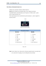
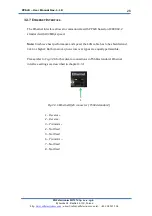
Connector Interface
“Analog remote”
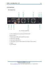
(Fig.3.3.4, a reference F) used to connect
external protection interlock and to control I/O of the power supply. Standard
Dsub25 female type connector type.
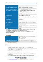
Pin outs and functions description:
1
25
Fig. 3.3.4 I/O Dsub25 pinouts
Pin No
1
2
3
4
5
6
7
8
9
AO
Analogue Output for output current measurement
I_OUT
; 0…5V (
0…
3000 mA ); Max load: 50mA
AO
Analogue Output for output power measurement
P_OUT
; 0…5V (
0…
1500W ); Max load: 50mA
AO
Analogue Output for output voltage measurement
V_OUT
; 0…
5
V ( 0…
1000 V ); Max load: 50mA
Main common
GND
signal for all of the Analogue signals
Main common
GND
signal for all of the Analogue signals
DI
Digital Input signal for external interlock
–
bridge this
signal with pin 5 or 20 or 25 to set the device to active
operation. Iin max: 5mA at 5V
DI
Digital Input
–
optocoupler type. This pin has to be
active to set HV ON. Input Voltage range: 0…5VDC. Input
active from 1,8
…5VDC; max current consumption 5mA at 5
VDC
IMPORTANT:
this input change the state on rising slop of
the signal only, to prevent automatic activation after
powering on. To set this pin active, Analog Control has to
be set in the user menu
–
ref. to chapter 4.3.1
AI
Analogue Input - set frequency in PulseDC mode
operation. 0..5V (
10…120 kHz –
optionally 10…300kHz)
,
Iin: 20mA max
Main common
GND
signal for all of the Digital signals


