PPS20
–
User Manual Rev. 1.10
EDFelectronics JRMM Sp. z o.o. sp.k.
Rybnicka 64, Radlin 44-310, Poland
; e-mail: info@edfelectronics.eu tel.: +48 604 343 504
23
10
11
12
13
14
15
16
17
18
19
20
21
22
23
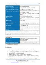
5VDC
source, max 500 mA. This signal should be applied
according to the digital ground
–
pin.4,5
DO
Digital Output - Toggle b5V & 0V to indicate
that target usage is below the threshold
Not used
Not used
Not used
DI
Digital Input
–
HV1 output selection; activated on
raising edge 5V
IMPORTANT:
other output HV2 needs to remain on 0 level
(0V, Pin 18). Otherwise rising edge on this input will not
take any effect.
Whatever is set on HV1 or HV2 pin during powering on,
unit always remains in previous/last output selection state.
To set this pin active, Analog Control has to be set in the
user menu as well
–
ref. to chapter 4.3.1
DI
Digital Input
–
optocoupler type. This pin has to be
active to set device into the Constant Power Mode. Input
Voltage range: 0…5VDC. Input active from
1,8
…5VDC; max
current consumption 5mA at 5 VDC.
IMPORTANT:
If this input stays in non active mode (0VDC)
together with the DI pin no. 17, unit will be switched into
the Constant Voltage Mode. To set this pin active, Analog
Control has to be set in the user menu
–
ref. to chapter 4.3.1
DI
Digital Input
–
optocoupler type. This pin has to be
active to set device into the Constant Current Mode. Input
Voltage range: 0…5VDC. Input active from 1,8…5VDC; max
current consumption 5mA at 5 VDC
IMPORTANT:
If this input stays in non active mode (0VDC)
together with the DI pin no. 16, unit will be switched into
the Constant Voltage Mode. To set this pin active, Analog
Control has to be set in the user menu
–
ref. to chapter 4.3.1
DI
Digital Input
–
HV2 output selection; activated on
raising edge 5V
IMPORTANT:
other output HV1 needs to remain on 0 level
(0V, Pin 15). Otherwise rising edge on this input will not
take any effect.
Whatever is set on HV1 or HV2 pin during powering on,
unit always remains in previous/last output selection state.
To set this pin active, Analog Control has to be set in the
user menu as well
–
ref. to chapter 4.3.1
DI
Digital Input
–
operating mode selection: 0V = DC
operation mode; 5V = PulseDC operation mode
IMPORTANT:
To set this pin active, Analog Control has to
be set in the user menu
–
ref. to chapter 4.3.1
Main common
GND
signal for all of the Analogue signals
AI
Analogue Input - set duty cycle in PulseDC mode
operation. 0..5V ( 2 .. 70% ), Iin: 20mA max
DO
Digital Output
–
this output stays in the high state
(+5V), when High Voltage is activated
AI
Analogue Input - set output voltage, current or power;
up to selected mode at pin 16 and 17. Iin: 20mA max

