PPS20
–
User Manual Rev. 1.10
EDFelectronics JRMM Sp. z o.o. sp.k.
Rybnicka 64, Radlin 44-310, Poland
; e-mail: info@edfelectronics.eu tel.: +48 604 343 504
48
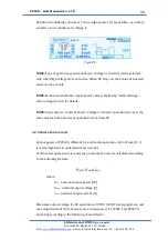
The following options are possible to set than:
1.
Power limit:
output power of PPS20 can be limited with this option
–
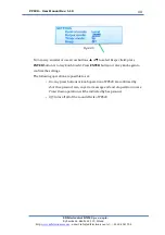
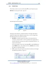
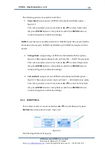
Fig.4.3.13
Turn rotary encoder or use arrow buttons
▲
or
▼
to select
Power Limit
tab; press
ENTER
button or rotary knob to edit. Press
ENTER
button or
rotary knob again to confirm the settings.
NOTE:
Power limit sets are different for DC or PulseDC mode. Max power limit for
DC mode can be set up to 1500W, and PulseDC up to 900W. See chapter 4.2.4 for
details.
2.
Voltage limit:
output voltage of PPS20 can be limited with this option
–
Fig.4.3.13.
Max ou
tput voltage can be set from 200 …. 1000 V for any mode
.
Turn rotary encoder or use arrow buttons
▲
or
▼
to select
Voltage Limit
tab; press
ENTER
button or rotary knob to edit. Press
ENTER
button or
rotary knob again to confirm the settings.
3.
Current limit:
output current of PPS20 can be limited with this option
–
Fig.4.3.13.
Max output current can be set from 5
….
3000 mA for any mode.
Turn rotary encoder or use arrow buttons
▲
or
▼
to select
Current Limit
tab; press
ENTER
button or rotary knob to edit. Press
ENTER
button or
rotary knob again to confirm the settings.
4.3.5
RAMPS
M
ENU
Turn rotary encoder or use arrow buttons
▲
or
▼
to select
Ramps
tab; press
ENTER
button rotary knob to edit
–
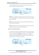
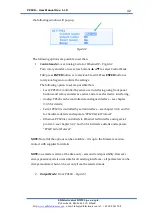
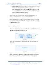
Fig 4.3.14
Fig.4.3.14
the following window will pup-up:

