PPS20
–
User Manual Rev. 1.10
EDFelectronics JRMM Sp. z o.o. sp.k.
Rybnicka 64, Radlin 44-310, Poland
; e-mail: info@edfelectronics.eu tel.: +48 604 343 504
36
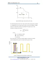
where:
P
PK
, U
PK
, I
PK
–
peak value of power, voltage and current, respectively
t
–
pulse width
,
T
–
pulse repetition interval
.
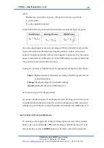
In the table below are presented relations between peak/average/rms power.
Peak Power
Average Power
RMS Power
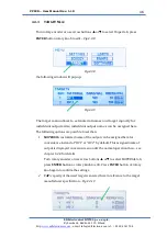
𝑃
𝑃𝐾
= 𝑈
𝑃𝐾
𝐼
𝑃𝐾
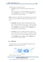
𝑃
𝐴𝑉
= 𝑃
𝑃𝐾
𝑡
𝑇
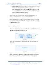
𝑃
𝑅𝑀𝑆
= 𝑃
𝑃𝑘
√
𝑡
𝑇
Since the output signal of current and voltage of PPS20 in PulseDC mode are like
square wave, (waves with distorted, irregular patterns
—
spikes, pulse trains,
squares, triangles, sawtooths and any other ragged or angular waves) the output
power is calculated as a RMS value of it. Thus, RMS determine power which is the
true electrical power delivered to the load.
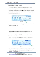
During the operation in PulseDC mode, the parameters displayed on the LDC are:
Power:
displayed power is calculated according to the RMS power formula
as described above,
Voltage:
displayed voltage is a peak pulse voltage,
Current:
displayed current is a RMS value of it.
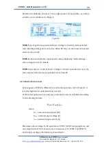
Refer also to Fig.4.2.3 for display details
For proper calculation power from displayed values of voltage and current, some
recalculation should be done. Since the current is displayed as a RMS value and
voltage as a peak value, the voltage should be also calculated as a RMS value of it.
4.2.5.
C
ONSTANT
V
OLTAGE
O
PERATION
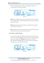
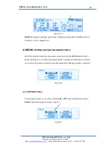
To operate power supply with Constant Voltage Operation, turn rotary encoder
knob or use arrow buttons
▲
or
▼
to select voltage in
SET
field (
Fig.4.2.8
) and
then press the encoder or
ENTER
button to edit mode
–
this will turn selected


