background image

 PPS20 

 User Manual Rev. 1.10 


EDFelectronics JRMM Sp. z o.o. sp.k. 

Rybnicka 64, Radlin 44-310, Poland


http: 

www.edfelectronics.com

 ; e-mail: info@edfelectronics.eu tel.:  +48 604 343 504


37 

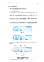
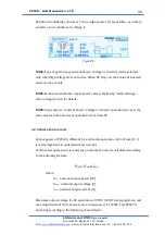
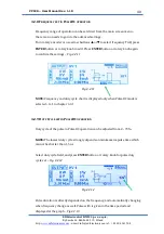
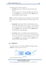
field into the blinking ( about 1/s ). Now output voltage set is possible 

 use 

rotary encoder or arrow buttons to change it. 


Fig. 4.2.8 


NOTE:

 Type of operation ( Constant Power, Voltage or Current ) can be selected 

only when high voltage HV is not active. When HV stays on, then value of selected 
mode can be set only. 


NOTE:

 Maximum adjustable output voltage 

value is limited by “Limit Settings” –


refer to chapter 4.3.4 for details. 
 

NOTE:

 Input data for Constant Power, Voltage or Current operation are set in the 

same way for both of mode of operation: DC or PulseDC 

4.2.6.


C

ONSTANT 

C

URRENT 

O

PERATION


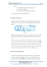
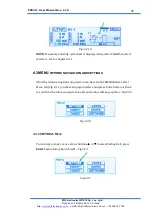
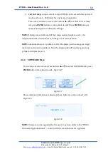
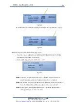
To operate power supply with Constant Current Operation, turn rotary encoder 

knob or use arrow buttons 

 or

 to select output current in 

SET

 field (

Fig.4.2.9

and then press the encoder or 

ENTER

 button to edit mode 

 this will turn 

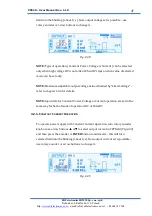
selected field into the blinking (about 1/s). Now output current set is possible 


use rotary encoder or arrow buttons to change it. 


Fig. 4.2.9 


Summary of Contents for PPS20

Page 1: ...d http www edfelectronics com e mail info edfelectronics eu tel 48 604 343 504 Magnetron Power Supply PPS20 User Manual April 2021 Rev 1 10 EXCECUTIVE SUMMARY The document contains a detailed description of the start up configuration interfacing of the power supply ...

Page 2: ...of contents liftings 1 3 2019 07 21 JL I O interface section updated to proper data 1 4 2019 10 09 JL Interface configuration sections added 1 5 2020 02 28 JL Power Calculation in DCpulse mode chapter upgrade 1 6 2020 03 18 JL Gramma corrections at page 7 and I O pinout description improve electric specification corrected 2 3 1 7 2020 04 29 JL Some data corrections 1 8 2020 06 05 JL Correction wit...

Page 3: ...5 Interfaces 14 2 5 1 I O interface 14 2 5 2 UART RS232 RS485 14 2 5 3 ETHERNET IP 14 3 Installation 15 3 1 Unpacking 15 3 2 Mechanical Installation 15 3 2 1 Rack Installation 16 3 3 Connecting 17 3 3 1 Rear Panel 17 17 3 3 3 Grounding 19 3 3 4 High Voltage Connectors HV1 and HV2 20 3 3 5 Interface Connector Analog remote 22 3 3 6 Serial Interface Connector 25 3 3 7 Ethernet Interface 26 4 Using t...

Page 4: ...in PulseDC operation 40 4 3 MENU options navigation and settings 41 4 3 1 SETTINGS Menu 41 4 3 2 SCREEN Menu 45 4 3 3 TARGET Menu 46 4 3 4 LIMITS Menu 47 4 3 5 RAMPS Menu 48 4 3 6 SOFTWARE Menu 50 5 Interface configuration 51 5 1 Analog Interface Configuration 51 5 2 Serial RS232 485 Interface Configuration 51 5 3 Ethernet Interface Configuration 53 6 Maintenance and Service 55 6 1 Maintenance 55 ...

Page 5: ...t Voltage or Constant Current The main field of application is the formation of plasma processes The concept and design of the power supply allows for safe and reliable integration of complex process control systems The device is referred to as PPS20 in the remainder of this manual 1 2 LIABILITIES AND WARRANTY EDFelectronics JRMM company is not liable for damages resulting from improper use of the...

Page 6: ...cessary experience or who have been instructed by the end user of the product 1 4 2 ILLUSTRATION OF RESIDUAL DANGERS This Operating Manual illustrates safety notes concerning residual dangers as follows Information on preventing any kind of physical injury Information on preventing extensive equipment and environmental damage Information on correct handling or use Disregarding safety notes can lea...

Page 7: ...o the applicable safety regulations Also observe all safety notes given in this document and forward the information to all other users of the product In particular pay attention to the following safety notes Fig 1 0 1 Mains voltage Contact with live parts is extremely hazardous when any objects are introduced or any liquids penetrate into the device Make sure that no objects enter through the lou...

Page 8: ...l info edfelectronics eu tel 48 604 343 504 8 Improper use Improper use can damage the PPS20 Use the PPS20 only as intended by the manufacturer Improper installation and operation data Improper installation and operation data may damage the PPS20 Strictly adhere to the stipulated installation and operation data WARNING WARNING ...

Page 9: ...DATA 2 1 GENERAL DATA 2 1 1 MECHANICAL DATA Dimensions Width 483 mm Height 88 1 mm 2 HU Depth 395 mm See Fig 2 1 1 Net Weight 10 8 kg Installation 19 Rack standard or Bench Top unit Fig 2 1 1 Dimensions mm Note The image above is illustrative rear panel connectors may differ depending on the version of the device 2 1 2 AMBIENCE Temperature Storage 10 60 C Operation Temperature 5 40 C ...

Page 10: ...ODES There are three common operation modes manual control with 5 buttons user interface on the front panel software remote control with RS232 RS485 or Ethernet Interface All Read commands are accessible all the time Write commands are accessible only with activation of this function from the user menu see remote control for use hardware remote control with I O interface see Tab 3 3 0 This mode is...

Page 11: ...d specifications EN 61010 1 Safety requirements for electrical equipment for measurement control and laboratory use EN 61000 6 2 Electromagnetic compatibility generic immunity standard EN 61000 6 3 Electromagnetic compatibility generic emission standard 2 2 MAINS CONNECTION Voltage 195 to 250 VAC 1 phase operation Frequency 43 63 Hz Current consumption Max 8 A at 230V Power consumption Max 1800 W ...

Page 12: ...D x H 2U Rack Mounting Standard Weight 10 8 kg alternatively operation is also possible from two hot wires 3 phase systems providing the voltage between them does not exceed more than 250 VAC minimum power in Pulse mode strongly depends from cable length and output magnetron impedance I O control Analog Interface 25 Dsub male connector isolated up to 2000 V RMS 0 5V Analogue 0 24 VDC Digital Seria...

Page 13: ... Poland http www edfelectronics com e mail info edfelectronics eu tel 48 604 343 504 13 High acceptance output impedance ability to work with magnetrons of different sizes Suitable for working with one or two magnetrons User friendly interface with OLED display keypad and rotary encoder ...

Page 14: ...tal Outputs 6 OC type opto isolated 24 VDC No of Analog Inputs 3 voltage input type opto isolated 0 5VDC No of Analog Outputs 3 voltage output type opto isolated 0 5VDC Response time 100 ms max 2 5 2 UART RS232 RS485 Connector D Sub 9 female connector Transmission mode 2400 4800 9600 19200 38400 57600 115200 bits s Data Length 8 bit Parity Control none Stop Bit 1 Transmission Control none 2 5 3 ET...

Page 15: ...ess 4 Visually inspect the PPS20 for signs of damage Damaged product Putting a damaged product into operation can be extremely dangerous Never attempt to put a damaged product into operation Secure the damaged product from unintended operation Send a damage report to the haulage company or the insurer 3 2 MECHANICAL INSTALLATION PPS20 can be used in the following ways as a bench top device mounted...

Page 16: ... the device Make sure that the maximum permitted ambient temperature is not exceeded and that the air can flow freely through the louvers Do not expose the device to direct sunlight Protection class of the rack If the product is installed in a rack it is likely to lower the protection class of the rack protection from foreign bodies and water e g according to the EN 60204 1 regulations for switchi...

Page 17: ...04 343 504 17 3 3 CONNECTING 3 3 1 REAR PANEL A B B G G C D F H E Fig 3 3 0 Rear panel PPS20 A HV1 and HV2 output connectors type N 50 2 0 G1 07 B fans and filters C RS232 interface Dsub 9 female RS485 optionally D Ethernet interface RJ45 E main power socket IEC C13 F I O interface connector Dsub 25 female see chapter 3 3 5 for details G Fuses H grounding pin ...

Page 18: ...ration of the available connections and photographs of cables is described in the following sections 3 3 2 MAINS CONNECTION The mains connection is designed for a mains cable which contains IEC 320 C19 connector on the device side A mains cable is supplied with the device If the plug is not compatible with your wall socket you should replace it with a suitable mains cable Three conductor cable wit...

Page 19: ...onnect the European appliance connector of the mains cord with the mains connection of the device 2 Connect the plug of the mains cable with the wall socket Note If the device is installed in a switching cabinet the mains power can be supplied via a switchable central power distributor 3 3 3 GROUNDING Grounding screw Fig 3 3 0 the reference H should be used to connect the PPS20 with the main groun...

Page 20: ...ware user interface Please refer to chapter 4 3 0 1 2 Fig 3 3 2 HV connector N 50 2 0 G1 07 type 1 HV1 1000 VDC 2 HV2 1000 VDC Hazardous voltage After entering Operate mode HV LED indicator on the front panel is lit the connector develops voltage levels dangerous to life and health The device must be turned off and completely isolated before any work associated with connecting or disconnecting the...

Page 21: ...tel 48 604 343 504 21 Typical discharge voltage without the load is presented at Fig 3 3 3 Fig 3 3 3 Improper usage of the power supply See Chapter 1 1 can cause power supply to be damage and brings risk of HV hazard Power Supply has to be interlocked with vacuum threshold system to prevent HV present at the accessible parts see Fig 3 3 5 CAUTION T 4s ...

Page 22: ...ogue Output for output voltage measurement V_OUT 0 5V 0 1000 V Max load 50mA Main common GND signal for all of the Analogue signals Main common GND signal for all of the Analogue signals DI Digital Input signal for external interlock bridge this signal with pin 5 or 20 or 25 to set the device to active operation Iin max 5mA at 5V DI Digital Input optocoupler type This pin has to be active to set H...

Page 23: ...ol has to be set in the user menu ref to chapter 4 3 1 DI Digital Input optocoupler type This pin has to be active to set device into the Constant Current Mode Input Voltage range 0 5VDC Input active from 1 8 5VDC max current consumption 5mA at 5 VDC IMPORTANT If this input stays in non active mode 0VDC together with the DI pin no 16 unit will be switched into the Constant Voltage Mode To set this...

Page 24: ... for all of the Digital signals Main common GND signal for all of the Digital signals Tab 3 3 0 Analog remote connector description The minimum required wiring is external interlock mode configuration see Fig 3 3 5 Fig 3 3 5 Minimum required wiring Improper connection In the case of incorrect connection in accordance with Tab 3 3 0 and Fig 3 3 5 there is a danger of damage to the power supply CAUT...

Page 25: ...485 interface is Half Duplex type and requires a terminal resistor please refer to Fig 3 3 5 and Tab 3 3 1 The transmission protocol is described in separate document contact supplier for details if needed Pin 1 Fig 3 3 5 Serial connector Serial Interface RS 232 RS485 1 Not Used 2 RxT 3 TxT 4 Not Used 5 GND 6 7 8 9 Not Used 1 Not Used 2 B 3 A 4 Not Used 5 GND 6 7 8 9 Not Used Tab 3 3 1 Note If uni...

Page 26: ...on IEEE 802 2 standard with 100 MB s speed Note to achieve best performance and speed the LAN cable has to be shielded and Cat 6 or higher Both crossover non crossover types are equally permissible Please refer to Fig 3 3 6 for hardware connections in T568A standard Ethernet interface settings are described in chapter 4 3 1 1 Fig 3 3 6 Ethernet RJ45 connector T568A standard 1 Receive 2 Receive 3 T...

Page 27: ...ch Rocker type 2 membrane press keyboard 3 high voltage indicator HV 4 alphanumeric display LCD 5 power meter bar 6 rotary encoder with press button 4 1 1 MAIN POWER SWITCH Switching On the power button position I activates the main power circuit of the device There is no possibility that high voltages can appear on the output connectors before transition to Operate mode see Chap 4 2 1 Switching o...

Page 28: ...witches the power supply into the OPERATE or STAND BY mode HV On Off turn the high voltage ON OFF switch to OPERATE STANDBY mode Up Down user interface menu positions change ESC cancel the operation move one menu level up MENU ENTER this button has two functions a go to the Main menu b confirm current setting Fig 4 1 2 Press buttons description Risk of the electric shock All connection to the devi...

Page 29: ...multiline alphanumeric LCD display with character height of 12 9 mm The display has adjustable brightness and contrast see Chap 4 4 1 4 1 5 POWER BAR IDENTIFIER Maximum output power of the device is 1500W in DC mode and 900W in PulseDC mode This value is proportionally presented by the LED power bar identifier Three different colours green yellow and red additionally identify the power level High ...

Page 30: ...4 1 7 MAIN SCREEN DESCRIPTION Fig 4 1 1 No Description No Description 1 Actual output selection 6 PulseDC indicator 2 Set point 7 PulseDC frequency 3 Deposition time indication 8 Main Menu tab 4 Actual measurements 9 PulseDC duty cycle 5 TG indicator 10 Deposition remaining time The currently selected option is highlighted by selection mask Turn rotary encoder or use arrow buttons or to select req...

Page 31: ...utton and navigate between the options of a menu using the arrow keys or To enter the selected sub menu again press ENTER MENU button The current operation can be canceled at any time by pressing the ESC key Pressing this this key also goes back to the previous menu If there is no reaction further keypress for 30 s the display returns to the main menu The same interaction can be done using rotary ...

Page 32: ... sets field is displayed in inverted background color To edit selected option just press the Enter button or press Rotary Encoder Inverted background will start to blink continue Encoder rotation to set the value When its finished just press Enter or Encoder once more time inverted field will stop to blink Main menu interface can looks different up to the selecting mode operation DC mode or PulseD...

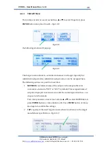
Page 33: ...referred according to used target for example For customized naming please refer to the chapter 4 3 3 To change the output selection turn rotary encoder knob or use arrow buttons or to select OUTPUT field Fig 4 2 4 and then press the encoder or ENTER button to edit mode this will turn selected field into the blinking about 1 s Now HV output selection is possible use rotary encoder or arrow buttons...

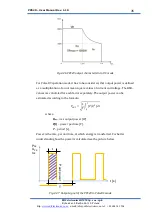
Page 34: ...ettings refer to chapter 4 3 4 for details NOTE Input data for Constant Power Voltage or Current operation are set in the same way for both of mode of operation DC or PulseDC 4 2 4 POWER CALCULATIONS Output power of PPS20 is different for each mode operation DC or PulseDC It is really important to understand how it works For DC mode operation it is really easy and output power is calculated accord...

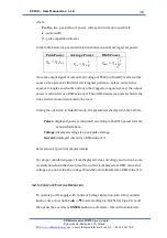
Page 35: ...fined as a multiplication of a root mean square values of current and voltage The RMS values are calculated for each factor separately The output power can be estimated according to the formula 𝑃𝑂𝑈𝑇 1 𝑇 𝑃 𝑡 2 𝑇 0 𝑑𝑡 where Pout rms output power W P t power per time V T period s Power is the rate per unit time at which energy is transferred For better understanding how the power is calculated see th...

Page 36: ...e of it Thus RMS determine power which is the true electrical power delivered to the load During the operation in PulseDC mode the parameters displayed on the LDC are Power displayed power is calculated according to the RMS power formula as described above Voltage displayed voltage is a peak pulse voltage Current displayed current is a RMS value of it Refer also to Fig 4 2 3 for display details Fo...

Page 37: ... mode can be set only NOTE Maximum adjustable output voltage value is limited by Limit Settings refer to chapter 4 3 4 for details NOTE Input data for Constant Power Voltage or Current operation are set in the same way for both of mode of operation DC or PulseDC 4 2 6 CONSTANT CURRENT OPERATION To operate power supply with Constant Current Operation turn rotary encoder knob or use arrow buttons or...

Page 38: ...ration Constant Power Voltage or Current can be selected only when high voltage HV is not active When HV stays on then value of selected mode can be set only NOTE Maximum adjustable current value is limited by Limit Settings refer to chapter 4 3 4 for details NOTE Input data for Constant Power Voltage or Current operation are set in the same way for both of mode of operation DC or PulseDC ...

Page 39: ... button or rotary knob to edit Press ENTER button or rotary knob again to confirm the settings Fig 4 2 10 Fig 4 2 10 To set the unit into no timer operation Timer Off set all timer values to 0 0 00 M s If timer is set to 0 then HV activation will activate HV output active as long as HV button is pressed again Any other sets will automatically set the unit into the time counter operation count down...

Page 40: ...ry knob again to confirm the settings Fig 4 2 11 Fig 4 2 11 NOTE Frequency and duty cycle chart is displayed only when PulseDC mode is selected ref to chapter 4 3 1 4 2 9 DUTY CYCLE SET IN PULSEDC OPERATION Duty cycle of the pulse in PulseDC operation can be adjusted from 2 70 NOTE The lowest duty cycle strongly depends on minimum impulse time which cannot be shorter than 1 5 us Select duty cycle ...

Page 41: ...s selected ref to chapter 4 3 1 4 3 MENU OPTIONS NAVIGATION AND SETTINGS All of the advanced options of operation can be set in the MENU folder Select Menu tab Fig 4 1 1 on the main page interface and press Enter button or Knob to switch to the sub menu operations Menu window will pop up than Fig 4 3 0 Fig 4 3 0 4 3 1 SETTINGS MENU Turn rotary encoder or use arrow buttons or to select Settings tab...

Page 42: ...el buttons and rotary encoder are active and are set for device interfacing Analog PPS20 can be controlled via analogue interface see chapter 3 3 5 for details Serial PPS20 is controlled by serial interface see chapter 3 3 6 and 5 2 for hardware details and separate PPS20 Serial Protocol Ethernet PPS20 is controlled via Ethernet LAN interface using serial protocol see chapter 3 3 7 and 5 3 for har...

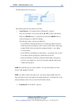
Page 43: ...DC voltage current or power operation see chapter 4 3 3 for details 3 Timer Mode Up or Down Fig 4 3 4 Fig 4 3 4 Turn rotary encoder or use arrow buttons or to select Timer Mode tab press ENTER button or rotary knob to edit Press ENTER button or rotary knob again to confirm the settings The following timer of operation are possible to set Up operation of PPS20 is active continually and follows cloc...

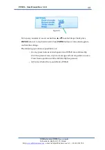
Page 44: ...buttons or to select Beeper field press ENTER button or rotary knob to edit Press ENTER button or rotary knob again to confirm the settings The following operation are possible to set On any press buttons or knob operation of PPS20 are confirmed by short beep sound also any error message end and of operation in case Timer Down operation will be indicated by beep sound Off turns off all of the soun...

Page 45: ...ill pup up Fig 4 3 7 The following options are possible to set than 1 Contrast the LCD contrast adjustable from 30 100 Fig 4 3 7 Turn rotary encoder or use arrow buttons or to select Contrast tab press ENTER button or rotary knob to edit Press ENTER button or rotary knob again to confirm the settings 2 Backlight the LCD brightness adjustable from 10 100 Fig 4 3 7 Turn rotary encoder or use arrow b...

Page 46: ...dividual outputs Also individual output names can be assigned here The following options are possible to set than 1 MATERIAL customized name of the output can be assigned here for convenience instead of HV1 or HV2 by default This assigned name of output is displayed on main screen under the normal operation than see chapter 4 2 2 for details Turn rotary encoder or use arrow buttons or to select MA...

Page 47: ...d as in the live time bar at the main screen see chapter 4 1 7 for details Remaining value can be reset at any time by choosing Clear tab Remaining value come back to the entered capacity value than Fig 4 3 11 Fig 4 3 11 Turn rotary encoder or use arrow buttons or to select CAP tab press ENTER button or rotary knob to edit Press ENTER button or rotary knob again to confirm the settings 4 3 4 LIMIT...

Page 48: ...4 for details 2 Voltage limit output voltage of PPS20 can be limited with this option Fig 4 3 13 Max output voltage can be set from 200 1000 V for any mode Turn rotary encoder or use arrow buttons or to select Voltage Limit tab press ENTER button or rotary knob to edit Press ENTER button or rotary knob again to confirm the settings 3 Current limit output current of PPS20 can be limited with this o...

Page 49: ... s See chapter 4 2 4 for details 1 Power ramp output power of PPS20 can fallow the power ramp set It can be set from 1 1500W S for DC mode operation or from 1 900 W S for PulseDC mode operation Units cannot be changed Turn rotary encoder or use arrow buttons or to select Power ramp tab press ENTER button or rotary knob to edit Press ENTER button or rotary knob again to confirm the settings 2 Volta...

Page 50: ...Ramps are activated all of the ramps works simultaneously it is independent from Constant Power Voltage or Current operation NOTE Sometimes there is a problem to start the plasma with some gases target materials and vacuum conditions Turn the Ramp option off and try again if any problem with plasma exist 4 3 6 SOFTWARE MENU Turn rotary encoder or use arrow buttons or to select SOFTWARE tab press E...

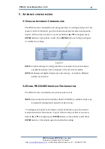
Page 51: ...ngs Fig 5 1 0 NOTE no other settings for Analog interface are needed For more hardware specification please refer to chapters 3 3 5 and 4 3 1 for details NOTE all Analog and digital outputs are active always even when different interface is selected 5 2 SERIAL RS232 485 INTERFACE CONFIGURATION The PPS20 can be controlled by one of serial port as well NOTE only one kind of serial interface RS232 or...

Page 52: ...an be selected from 2400 kBs 4800 kBs 9600 kBs 19 200 kBs 38 400 kBs 57 600 kBs 115 200 kBs device address can be selected from 1 247 Fig 5 2 2 NOTE no other settings for Serial interface are needed For more hardware specification please refer to chapters 3 3 6 and 4 3 1 for details NOTE unit address is used only for RS485 communication where this parameter has to be different for each the same de...

Page 53: ...ce go to the Control mode tab and select Ethernet mode Fig 5 3 0 Turn rotary encoder or use arrow buttons or to navigate press ENTER button or rotary knob to edit Press ENTER button or rotary knob again to confirm the settings Fig 5 3 0 Go to the Settings tab with the next step to configure main parameters Fig 5 3 1 Fig 5 3 1 There are four parameters to be set Fig 5 3 2 DHCP on off manual or auto...

Page 54: ...ronics JRMM Sp z o o sp k Rybnicka 64 Radlin 44 310 Poland http www edfelectronics com e mail info edfelectronics eu tel 48 604 343 504 54 NOTE as serial TCP ModBUS is implemented the 5th parameter which Port is is by default set to 502 ...

Page 55: ...quire any special maintenance work except filter cleaning and exchange Important Please check and exchange filters on the rear panel frequently Do not remove EMI filters To exchange the filters please use a flat screwdriver or knife and remove the upper fan cover Fig 6 1 0 Fig 6 1 0 Fig 6 1 1 Exchange the filters and put them back Please take care to close the cover correctly a click should be hea...

Page 56: ...tact the supplier for spare part numbers and pricing 6 1 1 CLEANING For cleaning the outside of the device a slightly moistened cloth will usually do Do not use any aggressive or abrasive cleaning agents Mains voltage Components inside of the PPS20 are components to mains voltage Do not insert any objects through the louvers of the device Protect the device from liquids Do not open the device ...

Page 57: ... required for storing the PPS20 and for shipping it to an EDFelectronics service center 7 2 STORAGE The PPS20 may only be stored in a dry room The following requirements must be met Ambient temperature 20 60 C Humidity as low as possible Preferably in an air tight plastic bag with a desiccant 7 3 DISPOSAL The product must be disposed of in accordance with the relevant local regulations for the env...

Page 58: ...nly when hardware interlock is missed during operation when HV ON Check hardware interlock connection or check external interlock source refer to section 3 3 5 4 No output voltage but maximum current appears Imax on LCD display The maximum current has been exceed Probably output shortcut check cable and the load connection 5 No HV LED identification on when HV ON max Current appears Probably outpu...

Page 59: ...st 42 Control Mode 39 Current Limit 45 Current ramp 47 D DC mode 30 40 Directive 11 Disposal 54 Duty Cycle 37 E Ethernet 50 F FREQUENCY 37 H Humidity 54 HV Output 30 I Interface 48 50 Interface configuration 48 IP address 50 L Limits 44 M Main Menu 30 Maintenance 52 Maintenance and Service 52 Material 43 Menu 39 ModBUS 51 O Output Mode 40 output voltage 32 P Packaging 54 Power Calculations 32 Powe...

Page 60: ...antee or remedies not specifically stated in this Limited Warranty This warranty does not cover ordinary wear and tear or expendable components EDFelectronics s obligation under this Limited Warranty is at EDFelectronics s option to repair or replace any defective equipment or parts of the equipment without charge to the purchaser which are returned shipping prepaid to the EDFelectronics facility ...

Reviews: