PPS20
–
User Manual Rev. 1.10
EDFelectronics JRMM Sp. z o.o. sp.k.
Rybnicka 64, Radlin 44-310, Poland
; e-mail: info@edfelectronics.eu tel.: +48 604 343 504
51
5.
I
NTERFACE CONFIGURATION
5.1
A
NALOG
I
NTERFACE
C
ONFIGURATION
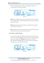
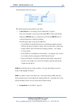
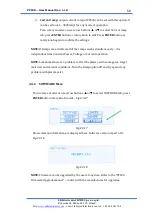
The PPS20 can be controlled by I/O analog interface. To configure I/O port as the
master control of the device go to the
Control mode
tab and select
Analog
mode
–
Fig. 5.1.0 Turn rotary encoder or use arrow buttons
▲
or
▼
to navigate; press
ENTER
button or rotary knob to edit. Press
ENTER
button or rotary knob again
to confirm the settings.
Fig.5.1.0
NOTE:
no other settings for Analog interface are needed. For more hardware
specification please refer to chapters 3.3.5 and 4.3.1 for details
NOTE:
all Analog and digital outputs are active always
–
even when different
interface is selected.
5.2
S
ERIAL
RS232/485
I
NTERFACE
C
ONFIGURATION
The PPS20 can be controlled by one of serial port as well.
NOTE:
only one kind of serial interface (RS232 or RS485) is available and it is up
to hardware configuration upon the order process.
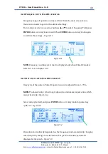
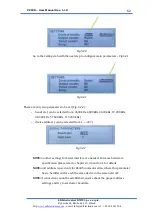
To configure serial port as the master control of the device go to the
Control
mode
tab and select
Serial
mode
–
Fig. 5.2.0 Turn rotary encoder or use arrow
buttons
▲
or
▼
to navigate; press
ENTER
button or rotary knob to edit. Press
ENTER
button or rotary knob again to confirm the settings.

