background image

Installing the Switch

3-6

3

Connecting to the Console Port 

The DB-9 serial port on the switch’s front panel is used to connect to the switch for 
out-of-band console configuration. The on-board configuration program can be 
accessed from a terminal or a PC running a terminal emulation program. The pin 
assignments used to connect to the serial port are provided in the following table.

Figure 3-6  Serial Port (DB-9 DTE) Pin-Out

Wiring Map for Serial Cable

The serial port’s configuration requirements are as follows:
•  Default Baud rate—9,600 bps
•  Character Size—8 Characters
•  Parity—None
•  Stop bit—One
•  Data bits—8

Table 3-1  Serial Cable Wiring

Switch’s 9-Pin 

Serial Port

Null Modem

PC’s 9-Pin 

DTE Port

2 RXD (receive data)

<---------------------------- 3 TXD (transmit data)

3 TXD (transmit data)

-----------------------------> 2 RXD (receive data)

5 SGND (signal ground) ------------------------------ 5 SGND (signal ground)
No other pins are used.

1

5

6

9

Summary of Contents for ES3526S

Page 1: ...www edge core com Installation Guide Powered by Accton ES3526S 24 Port 100BASE FX Fast Ethernet Switch ...

Page 2: ......

Page 3: ...Installation Guide Fast Ethernet Switch FTTH Switch with 24 100BASE FX Single fiber WDM SC Ports and 2 Combination 1000BASE T SFP Uplink ports ...

Page 4: ...ES3526S E082005 R01 150200052900A ...

Page 5: ......

Page 6: ...Installation Guide Fast Ethernet Switch FTTH Switch with 24 100BASE FX Single fiber WDM SC Ports and 2 Combination 1000BASE T SFP Uplink ports ...

Page 7: ...ES3526S E082005 R01 150200052900A ...

Page 8: ... from digital apparatus as set out in the interference causing equipment standard entitled Digital Apparatus ICES 003 of the Department of Communications Cet appareil numérique respecte les limites de bruits radioélectriques applicables aux appareils numériques de Classe A prescrites dans la norme sur le matériel brouilleur Appareils Numériques NMB 003 édictée par le ministère des Communications C...

Page 9: ...93 1 A m at frequency 50 Hz Voltage dips short interruptions and voltage variations immunity test according to EN 61000 4 11 1994 95 Reduction 10 ms 30 Reduction 500 ms 95 Reduction 5000 ms LVD EN60950 1 2001 When using a fiber optic port never look at the transmit laser while it is powered on Also never look directly at the fiber TX port and fiber cable ends when they are powered on Ne regardez j...

Page 10: ...powered from IT supplies If your supplies are of IT type this unit must be powered by 230 V 2P T via an isolation transformer ratio 1 1 with the secondary connection point labelled Neutral connected directly to earth ground Impédance à la terre Power Cord Set U S A and Canada The cord set must be UL approved and CSA certified The minimum specifications for the flexible cord are No 18 AWG not longe...

Page 11: ...érou uniquement Ce groupe ne peut pas être alimenté par un dispositif à impédance à la terre Si vos alimentations sont du type impédance à la terre ce groupe doit être alimenté par une tension de 230 V 2 P T par le biais d un transformateur d isolement à rapport 1 1 avec un point secondaire de connexion portant l appellation Neutre et avec raccordement direct à la terre masse Cordon électrique Il ...

Page 12: ...wird geprüft werden Schweiz Dieser Stromstecker muß die SEV ASE 1011Bestimmungen einhalten Europe Das Netzkabel muß vom Typ HO3VVF3GO 75 Mindestanforderung sein und die Aufschrift HAR oder BASEC tragen Der Netzstecker muß die Norm CEE 7 7 erfüllen SCHUKO Warning This product does not contain any serviceable user parts Warning Installation and removal of the unit must be carried out by qualified pe...

Page 13: ...als in this product Documentation All printed documentation for this product uses biodegradable paper that originates from sustained and managed forests The inks used in the printing process are non toxic Purpose This guide details the hardware features of the ES3526S switch including its physical and performance related characteristics and how to install it Achtung Dieses Produkt enthält keine Te...

Page 14: ...dministratoren mit Erfahrung im Netzwerkmangement Sie sollten mit Switch und Netzwerkkonzepten vertraut sein Related Publications The following publication gives specific information on how to operate and use the management functions of the switch The Fast Ethernet Switch Management Guide Also as part of the switch s firmware there is an online web based help that describes all management related ...

Page 15: ...viii ...

Page 16: ...nd Benefits 1 6 Connectivity 1 6 Performance 1 7 Management 1 7 Chapter 2 Network Planning 2 1 Fiber To The Home FTTH 2 1 Application Examples 2 1 Downlink Fiber Connections 2 2 Uplink SFP Connections 2 3 Management Connections 2 4 Making Private VLAN Connections 2 5 Application Notes 2 6 Chapter 3 Installing the Switch 3 1 Selecting a Site 3 1 Equipment Checklist 3 1 Package Contents 3 1 Optional...

Page 17: ...on Domain 4 5 Appendix A Troubleshooting A 1 Diagnosing Switch Indicators A 1 Power and Cooling Problems A 2 Installation A 2 In Band Access A 2 Appendix B Cables B 1 Twisted Pair Cable and Pin Assignments B 1 10 100BASE TX Pin Assignments B 2 Straight Through Wiring B 2 Crossover Wiring B 3 1000BASE T Pin Assignments B 3 Appendix C Specifications C 1 Physical Characteristics C 1 Compliances C 2 S...

Page 18: ...nnections 2 5 Figure 3 1 Attaching the Brackets 3 2 Figure 3 2 Installing the Switch in a Rack 3 3 Figure 3 3 Attaching the Adhesive Feet 3 3 Figure 3 4 Installing an SFP Transceiver 3 4 Figure 3 5 Power Receptacle 3 5 Figure 3 6 Serial Port DB 9 DTE Pin Out 3 6 Figure 4 1 Making RJ 45 Port Connections 4 2 Figure 4 2 Making SC Port Connections 4 4 Figure 4 3 Making SFP Port Connections 4 4 Figure ...

Page 19: ...ngth 4 5 Table 4 2 Maximum 1000BASE SX Fiber Optic Cable Lengths 4 5 Table 4 3 Maximum 1000BASE LX Fiber Optic Cable Length 4 5 Table 4 4 Maximum Fast Ethernet Cable Lengths 4 5 Table 4 5 Maximum Ethernet Cable Length 4 5 Table A 1 Troubleshooting Chart A 1 Table B 1 10 100BASE TX MDI and MDI X Port Pinouts B 2 Table B 2 1000BASE T MDI and MDI X Port Pinouts B 4 ...

Page 20: ...t port This port is for secure in band management via a Web browser SNMP RMON or Telnet The DB 9 serial console port is for direct connection to a PC using the console cable that is supplied with the switch A wide range of management features are supported including tagged VLANs multicast filtering Class of Service CoS priority queuing bandwidth rate limiting and Private VLAN port isolation The sw...

Page 21: ...edded management software or via SNMP applications To manage the switch you can make a direct connection to the DB 9 console port out of band or you can manage the switch through its RJ 45 Management port in band using Telnet the on board Web agent or network management software The management agent provides a wide range of advanced performance enhancing features Port based and private VLANs provi...

Page 22: ...e SFP slots If an SFP transceiver purchased separately is installed in a slot and has a valid link on the port the associated RJ 45 port is disabled These ports support automatic MDI MDI X operation so you can use straight through cables for all network connections to PCs or servers or to other switches See Twisted Pair Cable and Pin Assignments on page B 1 Both ports support auto negotiation so t...

Page 23: ...mented Reset Button Pressing the reset button reboots the switch Console Port The console port on the switch s front panel is a DB 9 connector that enables a connection to a terminal for performing switch monitoring and configuration functions The terminal may be a PC or workstation running terminal emulation software or a terminal configured as a Data Terminal Equipment DTE connection A null mode...

Page 24: ...ination Ports 25 26 Link Act On Flashing Amber Port has established a valid 10 100 Mbps network connection Flashing indicates activity On Flashing Green Port has established a valid 1000 Mbps network connection Flashing indicates activity Off There is no valid link on the port Table 1 2 System Status LEDs LED Condition Status Power On Green The unit s internal power supply is operating normally On...

Page 25: ...nnections up to 15 km Auto negotiation enables each 10 100 1000BASE T port to automatically select the optimum communication mode half or full duplex if this feature is supported by the attached device otherwise the port can be configured manually Unshielded UTP cable supported on all RJ 45 ports Category 3 or better for 10 Mbps connections Category 5 or better for 100 Mbps connections and Categor...

Page 26: ...ad of Line blocking prevention Performance Transparent bridging Aggregate bandwidth up to 8 8 Gbps Filtering and forwarding at line speed Provides Store and Forward switching Supports IEEE 802 3 2002 full duplex flow control Management At a glance LEDs for easy troubleshooting Management agent Supports Telnet SNMP and Web based interface Dedicated management port for in band access Hardware assist...

Page 27: ...Introduction 1 8 1 ...

Page 28: ...00BASE FX full duplex single fiber single mode cable connections that run from the service provider s central office CO directly to Media Converters installed at subscriber premises Each single mode fiber connection can be run up to a distance of 15 km from the CO The switch also provides two 1000BASE T SFP uplink ports for connections to other switches or routers at the CO The Media Converter is ...

Page 29: ...a Converter Customer Premises Equipment CPE is installed inside a subscriber s premises so there are no active outside components between the CO and the end user The figure below illustrates a basic switch to CPE connection Figure 2 1 Downlink Fiber Connections CPE 100BASE FX full duplex single fiber WDM link to CO up to 15 km Subscriber s Home Central Office CO 10 100BASE TX UTP connection to com...

Page 30: ... switch or router at the CO Besides balancing the load across each port in the trunk the additional port provides redundancy by taking over the load if the other port in the trunk fails The figure below illustrates the ES3526S connecting to switches with UTP cable Figure 2 2 Uplink SFP Connections Layer 2 3 Switch Link to Internet POP 1000BASE T UTP trunk connection to Layer 2 3 switch up to 100 m...

Page 31: ... band management access This 10 100BASE TX port can be connected to the CO Ethernet LAN for network management The figure below illustrates management port connections to ES3526S switches Figure 2 3 RJ 45 Management Port Connections Ethernet Switch Management Station 10 100BASE TX UTP connections to Ethernet switch up to 100 m ES3526S Switches ES3526S ES3526S ES3526S ...

Page 32: ...t based security for each subscriber Furthermore the switch can control the bandwidth of downlink connections using traffic rate limiting Each fiber port downlink can be limited to values from 1 Mbps to 100 Mbps in increments of 1 Mbps depending on the needs of the individual user The service provider can then charge subscribers according to the bandwidth provided The figure below illustrates Priv...

Page 33: ...verall performance for the segment attached to the hub 3 For network applications that require routing between dissimilar network types you can attach switch units directly to a router 4 As a general rule the length of fiber optic cable for a single switched link should not exceed 1000BASE SX 550 m 1805 ft using multimode fiber 1000BASE LX 5 km 3 2 miles using single mode fiber 100BASE LH 70 km 43...

Page 34: ...ted away from power lines fluorescent lighting fixtures and other sources of electrical interference such as radios transmitters etc Make sure that a separate grounded power outlet that provides 100 to 240 VAC 50 to 60 Hz is within 2 44 m 8 feet of each device and is powered from an independent circuit breaker As with any equipment using a filter or surge suppressor is recommended Equipment Checkl...

Page 35: ...ture Since the temperature within a rack assembly may be higher than the ambient room temperature check that the rack environment temperature is within the specified operating temperature range See page C 2 Mechanical Loading Do not place any equipment on top of a rack mounted unit Circuit Overloading Be sure that the supply circuit to the rack assembly is not overloaded Grounding Rack mounted equ...

Page 36: ...them in the rack one below the other in any order Desktop or Shelf Mounting 1 Attach the four adhesive feet to the bottom of the first switch Figure 3 3 Attaching the Adhesive Feet 2 Set the device on a flat surface near an AC power source making sure there are at least two inches of space on all sides for proper air flow 26 Link Act PoE 25 26 PWR Diag Stacking Mode PoE Link 25 ES3526S E S 35 26 S...

Page 37: ... lasers are compliant with the requirements of a Class 1 Laser Product and are inherently eye safe in normal operation However you should never look directly at a transmit port when it is powered on Note SFP transceivers are hot swappable You do not need to power off the switch before installing or removing a transceiver You can install an SFP transceiver as described below 1 Insert the SFP transc...

Page 38: ...cket Note For International use you may need to change the AC line cord You must use a line cord set that has been approved for the receptacle type in your country 3 Check the front panel LEDs as the device is powered on to be sure the Power LED is lit If not check that the power cable is correctly plugged in 4 If you have purchased a Redundant Power Supply connect it to the switch and to an AC po...

Page 39: ...onnect to the serial port are provided in the following table Figure 3 6 Serial Port DB 9 DTE Pin Out Wiring Map for Serial Cable The serial port s configuration requirements are as follows Default Baud rate 9 600 bps Character Size 8 Characters Parity None Stop bit One Data bits 8 Table 3 1 Serial Cable Wiring Switch s 9 Pin Serial Port Null Modem PC s 9 Pin DTE Port 2 RXD receive data 3 TXD tran...

Page 40: ...ns Category 5 or better cable is required for 10BASE T Category 3 or better cable can be used For 1000BASE T connections Category 5 5e or 6 recommended cable is required with all four wire pairs connected You should also test the cable installation for IEEE 802 3 2002 Gigabit Ethernet compliance See Twisted Pair Cable and Pin Assignments on page B 1 Cabling Guidelines The 1000BASE T RJ 45 ports al...

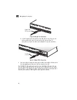
Page 41: ...rm to FCC standards 1 Attach one end of a twisted pair cable segment to the device s RJ 45 connector Figure 4 1 Making RJ 45 Port Connections 2 Attach the other end to an available RJ 45 port on the switch Make sure each twisted pair cable does not exceed 100 meters 328 ft in length 3 As each connection is made the green Link Act LED corresponding to each port will light to indicate that the conne...

Page 42: ...ring safety please make sure that it can function at a temperature that is not less than the recommended maximum operational temperature of the product You must also use an approved Laser Class 1 SFP transceiver Hinweis Bei der Wahl eines Glasfasertransceivers muß für die Beurteilung der Gesamtsicherheit beachtet werden das die maximale Umgebungstemperatur des Transceivers für den Betrieb nicht ni...

Page 43: ...FP Port Connections 4 As a connection is made check the Link Act LED on the switch s front panel for the corresponding port to be sure that the connection is valid The 100BASE FX fiber optic ports operate only at 100 Mbps full duplex You can run each single mode fiber link up to a maximum of 15 kilometers from the central office However note that power budget constraints must also be considered wh...

Page 44: ...ngth Category 5 5e or better 100 ohm UTP or STP 100 m 328 ft Table 4 2 Maximum 1000BASE SX Fiber Optic Cable Lengths Fiber Size Fiber Bandwidth Maximum Cable Length 62 5 125 micron 160 MHz km 2 220 m 7 722 ft 200 MHz km 2 275 m 7 902 ft 50 125 micron 400 MHz km 2 500 m 7 1641 ft 500 MHz km 2 550 m 7 1805 ft Table 4 3 Maximum 1000BASE LX Fiber Optic Cable Length Fiber Size Fiber Bandwidth Maximum C...

Page 45: ...Making Network Connections 4 6 4 ...

Page 46: ...ify that the switch and attached device are powered on Be sure the cable is correctly plugged into both the switch and corresponding device Verify that the proper cable type is used and its length does not exceed specified limits Check the port on the attached device and cable connections for possible defects Replace the defective device or cable if necessary Remote Error indicator is on amber The...

Page 47: ...environment where you are sure that all the other components are functioning properly In Band Access You can access the management agent in the switch from anywhere within the network attached to the management port using Telnet a Web browser or other network management software However you must first configure the switch with a valid IP address subnet mask and default gateway If you have trouble ...

Page 48: ... 45 connector must be attached to both ends of the cable Caution Each wire pair must be attached to the RJ 45 connectors in a specific orientation Caution DO NOT plug a phone jack connector into any RJ 45 port Use only twisted pair cables with RJ 45 connectors that conform with FCC standards The Figure B 1 illustrates how the pins on the RJ 45 connector are numbered Be sure to hold the connectors ...

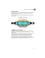
Page 49: ... must be straight through You must connect all four wire pairs to support Gigabit Ethernet as shown in the following diagram Figure B 2 Straight through Wiring Table B 1 10 100BASE TX MDI and MDI X Port Pinouts Pin MDI Signal Name MDI X Signal Name 1 Transmit Data plus TD Receive Data plus RD 2 Transmit Data minus TD Receive Data minus RD 3 Receive Data plus RD Transmit Data plus TD 6 Receive Data...

Page 50: ...ork connections to PCs or servers or to other switches or hubs The table below shows the 1000BASE T MDI and MDI X port pinouts These ports require that all four pairs of wires be connected Note that for 1000BASE T operation all four pairs of wires are used for both transmit and receive Use 100 ohm Category 5 5e or 6 unshielded twisted pair UTP or shielded twisted pair STP cable for 1000BASE T conn...

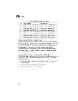
Page 51: ...000BASE T there are basically three measures that can be applied to try and correct the problem 1 Replace any Category 5 patch cables with high performance Category 5e or Category 6 cables 2 Reduce the number of connectors used in the link 3 Reconnect some of the connectors in the link Table B 2 1000BASE T MDI and MDI X Port Pinouts Pin MDI Signal Name MDI X Signal Name 1 Bi directional Data One P...

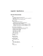
Page 52: ...UTP cable Categories 3 or better 100BASE TX RJ 45 100 ohm UTP cable Category 5 or better 1000BASE T RJ 45 100 ohm UTP cable Category 5 5e or 6 Fiber Transceiver Specifications Fiber Cable ITU T G 652 single fiber single mode WDM Wavelengths 1550 nm transmit 1130 nm receive Data Rate 100 Mbps full duplex Transmit Power 14 to 8 dBm Receive Power 30 to 8 dBm Optical Power Budget 16 dB Range Up to 15 ...

Page 53: ...g 5 to 95 Power Supply Internal auto ranging transformer 100 to 240 VAC 50 to 60 Hz Power Consumption 100 Watts maximum Heat Dissipation 340 BTU hr maximum Maximum Current 0 9A 110 VAC 0 4A 240 VAC Compliances CE Mark Emissions FCC Class A Safety CSA CSA C22 2 NO60950 1 UL60950 1 TUV GS EN60950 1 CB IEC60950 1 Switch Features Forwarding Mode Store and forward ...

Page 54: ...Management Web Telnet SSH or SNMP manager Out of Band Management RS 232C DTE DB 9 console port Software Loading TFTP in band or XModem out of band Standards IEEE Std 802 3 2002 IEEE 802 1D Bridging IEEE 802 3 2002 Ethernet Fast Ethernet Gigabit Ethernet Full duplex flow control Link Aggregation Protocol ISO IEC 8802 3 ...

Page 55: ...Specifications C 4 C ...

Page 56: ...reichende Beluftung aufgestellt werden Für das Installieren die Kabelverlegung und für Wartungen und Reparaturen leicht zugänglich sein Die LED Statusanzeigedioden mussen stets klar und leicht sichtbar sein Sicherstellen dass das verdrehte Kabel stets weg von anderen Stromkabeln Neonleuchteinrihtungen und anderen Quellen von moglichen elektrischen Storungen verlegt wird wie z B von Radios und Tran...

Page 57: ...2 Mechanische Last Stellen Sie kein Gerät auf eine Rack Montageeinheit Stromüberlastung Stellen Sie sicher dass der Netzkreis der Rackeinheit nicht überlastet wird Erdung Die Rack Montageeinheit muss richtig geerdet werden Besondere Acht sollten Sie bei Verbindungen geben die nicht direkt zum Netz führen So montieren Sie Geräte an ein Rack 1 Befestigen Sie die Metallwinkel mit den im Metallwinkel ...

Page 58: ...e 1000BASE SX IEEE 802 3z specification for Gigabit Ethernet over two strands of 50 125 or 62 5 125 micron core fiber cable 1000BASE T IEEE 802 3ab specification for Gigabit Ethernet over two pairs of Category 5 5e or better 100 ohm UTP cable Auto Negotiation Signalling method allowing each node to select its optimum operational mode speed and duplex based on the capabilities of the node to which ...

Page 59: ...l cable The successor IEEE 802 3 standard provides for integration into the OSI model and extends the physical layer and media with repeaters and implementations that operate on fiber thin coax and twisted pair cable Fast Ethernet A 100 Mbps network communication system based on Ethernet and the CSMA CD access method Fast Ethernet Switch Device that provides a full 100 Mbps bandwidth or either 10 ...

Page 60: ...nks IEEE 802 3z Defines CSMA CD access method and physical layer specifications for 1000BASE Gigabit Ethernet LAN Segment Separate LAN or collision domain Layer 2 Data Link layer in the ISO 7 Layer Data Communications Protocol This is related directly to the hardware interface for network devices and passes on traffic based on MAC addresses Layer 3 Network layer in the ISO 7 Layer Data Communicati...

Page 61: ... forwards them to all ports contained within the designated multicast VLAN group Network Diameter Wire distance between two end stations in the same collision domain Out of Band Management Management of the network from a station not attached to the network Port Mirroring A method whereby data on a target port is mirrored to a monitor port for troubleshooting with a logic analyzer or RMON probe Th...

Page 62: ...erminal device over TCP IP TIA Telecommunications Industry Association Transmission Control Protocol Internet Protocol TCP IP Protocol suite that includes TCP as the primary transport protocol and IP as the network layer protocol Trivial File Transfer Protocol TFTP A TCP IP protocol commonly used for software downloads UTP Unshielded twisted pair cable Virtual LAN VLAN A Virtual LAN is a collectio...

Page 63: ...Glossary Glossary 6 ...

Page 64: ...fiber terminators 4 3 compliances safety C 2 connection examples 2 1 console port pin assignments 3 6 console port pin assignments 3 6 contents of package 3 1 cooling problems A 2 cord sets international 3 5 D desktop mounting 3 3 device connections 4 1 E electrical interference avoiding 3 1 equipment checklist 3 1 examples connections 2 1 F features C 3 management 1 7 switch 1 6 fiber cables 4 3 ...

Page 65: ...troubleshooting A 1 Q QoS 1 2 R rack mounting 3 2 rear panel receptacles 1 6 RJ 45 port connections 4 1 pinouts B 4 rubber foot pads attaching 3 3 S screws for rack mounting 3 2 single mode fiber optic cables 4 3 site selelction 3 1 SNMP agent 1 2 specifications compliances C 2 environmental C 2 physical C 1 power C 2 standards compliance C 2 IEEE C 3 status LEDs 1 4 surge suppressor using 3 1 swi...

Page 66: ......

Page 67: ...ES3526S E082005 R01 150200052900A ...

Reviews: