Troubleshooting Tips and Notes
Use of a multi-meter / voltage reader is recommended for proper diagnosis.
Determining the point at which power is not properly passing into or through a
component is the best method for determining component failure.
If the unit does not appear to be receiving power:
Ensure that the power source is providing the proper voltage to the unit.
When using 12V DC, the digital readout will show the factory setting 10.0V DC.
To ensure that suitable battery voltage can be maintained the controller has been
programmed to offer three (3) cut-out levels: 11.8, 10.7, and 10.0V DC.
When using 24V DC, the digital readout will show the factory setting 22.2V DC.
To ensure that suitable battery voltage can be maintained the controller has been
programmed to offer three (3) cut-out levels- 25.0, 23.5 & 22.2V DC. Check and
verify the power supply cord(s) are free from defects / damage.
Check for loose connections between power source and unit.
When inspecting internal components, always check for loose connections.
Summary of Contents for FP430
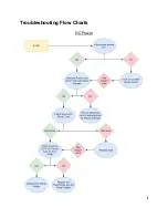
Page 7: ...Troubleshooting Flow Charts DC Power...
Page 8: ...AC Power...

