

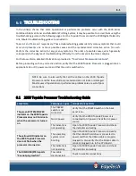


6.0: TROUBLESHOOTING
6-8
2000-DSS COMBINED SONAR
0009335_REV_D
6.3.7.2
No Sonar Data
If the sonar display doesn’t scroll, use the ‘scope sniffing’ approach as outlined in “Transmission
Verification” on page 5-18 to check transducer firing. If the transducers are firing, and the data link is
working, the problem is most likely related to the topside processor and/or data modem.
If the display scrolls but is blank and the transducers are firing, the problem most likely lies with either or
a combination of the tow vehicle receiver, transducer or its signal processing circuitry. Establish if the
problem is on a single channel or all channels.
If data is absent in all, or individual channels, check the T/R Switch and SSB boards. If the problem is with
a particular channel, also check the respective power amplifier and transducer element.
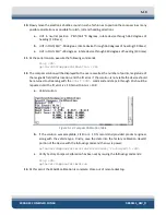
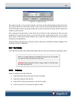
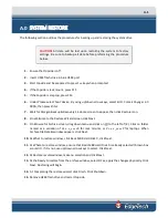
Connect to tow vehicle using REMOTE DESKTOP 192.9.0.101 login: administrator, password: admin . Sonar
application should be running and there should not be any errors posted to the window. Errors reported
could be: “No Sonar Device Found”, this will indicate that the CPU does not connect to the sonar processor
card. “IF_DIAG” the sonar processor has detected an error and will not run. Cycle power on tow vehicle
recheck error, if the error is still present check the cables running to and from the sonar interface card.
“HM_Sensors” this reports the 48 volts if this error is found check output of power distribution board in
tow vehicle and also the power on the power amps.
6.3.7.3
Power Supplies
Several power supplies and voltage regulators are located throughout the tow vehicle assembly. The main
ones are located on the Power Distribution board. The first supply converts the 400VDC tow cable voltage
to the ope48VDC supply. Other DC/DC converters running off the 48 volts generate the low level
operating supply voltages. No supplies are adjustable.
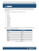
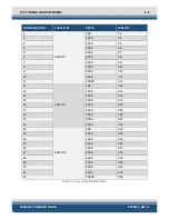
The following are the main voltage test points on the Power Distribution board.
Supply
Test Point
Return
+5 VDC +/-0.2V
TP7
TP12
+12 VDC +/-0.6V
TP8
TP12
-12 VDC +/-0.6V
TP9
TP12
+27 VDC +/-0.6V
TP10
TP12
+48 VDC +/-2.0V
TP4
TP5
Other voltages to check on the SSB board and labeled as such are:
Supply
+3.3 VDC +/-0.1
+5 VDC +/-0.2V
Summary of Contents for 2000-DSS
Page 20: ......
Page 56: ...Figure 4 2 2000 Digital Telemetry Link Electronics Block Diagram...
Page 57: ...Figure 4 3 2000 Digital Telemetry Link Wiring Diagram...
Page 59: ...Figure 4 4 Tow Vehicle Electronic Block Diagram...
Page 60: ...Figure 4 5 Tow Vehicle Interconnect Drawing...
Page 63: ...Figure 4 6 Armored Cable PMI Grip Unterminated Topside...
Page 64: ...Figure 4 7 Test Cable...
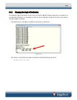
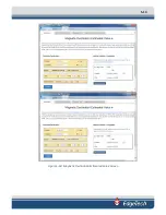
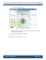
Page 77: ...5 13 Figure 5 16 Magnetic Declination Estimated Value Screen...
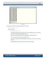
Page 79: ...5 15 getDeclination CR Figure 5 18...
Page 80: ......
Page 94: ......
Page 96: ......
Page 98: ......


