
1-4
2000-DSS COMBINED SONAR
0009335_REV_D
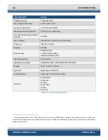
1.2.3
2000-DSS Tow Vehicle
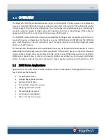
The 2000-DSS Tow Vehicle contains the side scan transducer arrays, the sub bottom transducer, and the
sub-bottom hydrophone arrays along with the electronics required to transmit and to receive the sonar
signals, to receive the downlink commands from the 2000 Topside Processor and to provide the uplink
side scan data, sensor data and status information to the 2000 Topside Processor. The tow vehicle is
available with a choice of 100/400 kHz or 300/600 kHz dual linear FM chirp operating frequencies for the
side scan sonar.
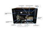
The sonar electronics are contained inside a single electronics bottle, which includes a double O-ring
sealed end cap on each end. The aft end cap contains bulkhead connectors for connecting the transducers,
the hydrophone arrays and optional equipment. The tow vehicle interfaces with the 2000 Topside
Processor over an Ethernet connection using digital subscriber line (ADSL) modems in both the tow vehicle
and the processor. The 2000-DSS Tow Vehicle is shown in
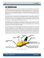
The 2000-DSS Tow Vehicle sub-bottom sonar operates over a frequency range of 2–16 kHz, has a 2000-
meter depth rating, and is designed primarily for applications requiring higher resolution sub-bottom
imagery. It is hydrodynamically stabilized and includes the sub-bottom transducer and two sub bottom
hydrophone arrays mounted under an acoustic baffle.
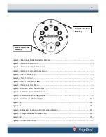
This assembly, along with the connecting cable harnesses and the electronics bottle, is mounted to a wing
plate and contained inside a two-piece fiberglass shell. The upper and lower halves of the shell bolt
directly to the wing plate. The aft section of the wing plate forms the horizontal tail fins, and a vertical tail
fin is attached to the upper half of the shell. Lead ballast is included inside the lower half. The port and
starboard side scan transducer arrays are mounted to the lower half of the shell, and a hinged tow bridle
provides the mechanical connection for the tow cable. The bridle can be adjusted fore and aft along a pair
of tow brackets, one port and one starboard, to accommodate different tow vehicle speeds and depths.
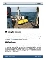
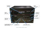
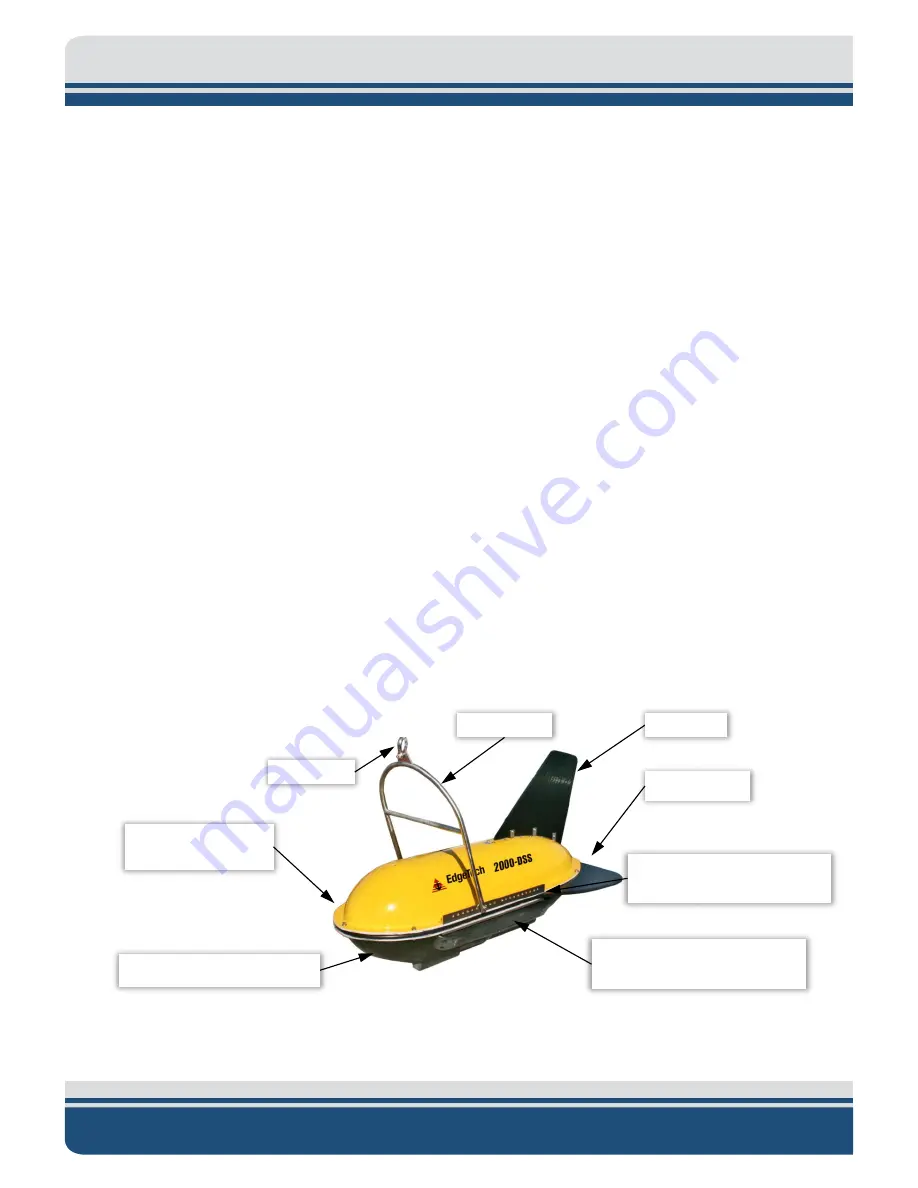
Figure 1-3: 2000-DSS Tow Vehicle
TAIL FIN
UPPER FIBERGLASS
SHELL
TOW BRIDLE
SHACKLE
LOWER FIBERGLASS SHELL
SIDE SCAN TRANSDUCER, ONE
STARBOARD AND ONE PORT
TOW BRACKET, ONE
STARBOARD AND ONE PORT
WING PLATE
Summary of Contents for 2000-DSS
Page 20: ......
Page 56: ...Figure 4 2 2000 Digital Telemetry Link Electronics Block Diagram...
Page 57: ...Figure 4 3 2000 Digital Telemetry Link Wiring Diagram...
Page 59: ...Figure 4 4 Tow Vehicle Electronic Block Diagram...
Page 60: ...Figure 4 5 Tow Vehicle Interconnect Drawing...
Page 63: ...Figure 4 6 Armored Cable PMI Grip Unterminated Topside...
Page 64: ...Figure 4 7 Test Cable...
Page 77: ...5 13 Figure 5 16 Magnetic Declination Estimated Value Screen...
Page 79: ...5 15 getDeclination CR Figure 5 18...
Page 80: ......
Page 94: ......
Page 96: ......
Page 98: ......


