
3-15
CAUTION!
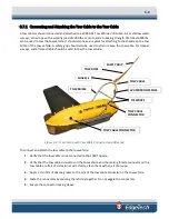
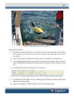
Do not allow the sub-bottom transducer on the tow vehicle to
continuously transmit in air for an extended period as damage to the
transducer could occur.
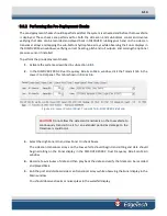
13.
From the Sonar menu, choose Sonar On. When the sonar is on, a check mark appears next to the
menu item.
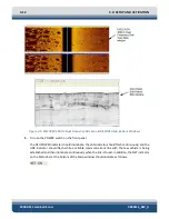
The transducers on the tow vehicle should begin transmitting and data should begin scrolling on
the Sonar display in the DISCOVER Sub-Bottom Main window.
14.
Listen for transmissions from the sub-bottom transducer and verify that they are present.
15.
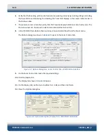
Tap the underside of the tow vehicle near the hydrophones with the handle of a screw driver
while observing the Sonar display in the DISCOVER Sub-Bottom Main window.
You should observe streaks or noise spikes in the waterfall display.
Summary of Contents for 2000-DSS
Page 20: ......
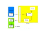
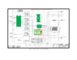
Page 56: ...Figure 4 2 2000 Digital Telemetry Link Electronics Block Diagram...
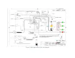
Page 57: ...Figure 4 3 2000 Digital Telemetry Link Wiring Diagram...
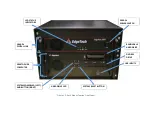
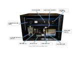
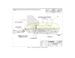
Page 59: ...Figure 4 4 Tow Vehicle Electronic Block Diagram...
Page 60: ...Figure 4 5 Tow Vehicle Interconnect Drawing...
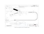
Page 63: ...Figure 4 6 Armored Cable PMI Grip Unterminated Topside...
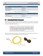
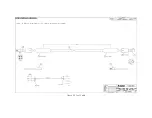
Page 64: ...Figure 4 7 Test Cable...
Page 77: ...5 13 Figure 5 16 Magnetic Declination Estimated Value Screen...
Page 79: ...5 15 getDeclination CR Figure 5 18...
Page 80: ......
Page 94: ......
Page 96: ......
Page 98: ......


