

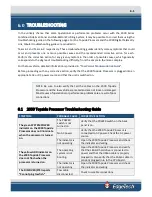
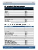


6.0: TROUBLESHOOTING
6-4
2000-DSS COMBINED SONAR
0009335_REV_D
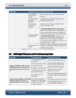
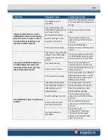
SYMPTOM
PROBABLE CAUSE
CORRECTIVE ACTION
The tow vehicle is faulty.
Verify tow vehicle on a different
2000 Topside Processor. Verify
2000 Topside Processor with a
different tow vehicle.
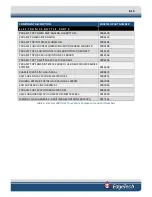
Table 6-2: 2000 Digital Telemetry Link Troubleshooting Guide
6.3
Tow Vehicle Troubleshooting Guide
The tow vehicle is a computer-controlled device. Therefore, to troubleshoot such a complex piece of
equipment to a sub-module level, one must have the proper test equipment and thorough knowledge of
the unit’s electrical operation plus hardware aspects. The purpose of this section is not to develop those
techniques nor provide a step-by-step procedure where one may start and end up at the point of failure.
It is to give an operator some familiarity with the electronic hardware. The following sections provide
some specific areas to check which are easily identifiable and certain clues as to what to look for in making
an educated guess as to the source of the problem. This is only down to the module or PCB level.
The tow vehicle is a software-controlled computer system. There are also some analog sections that
interface with the tow vehicle transducers. Being a digital device, many operating portions use the same
data and address lines a failure of one may result in a failure of all. This makes it very hard to isolate some
digital problems without the proper equipment and a thorough knowledge of the data flow. This
equipment is not normally found on a vessel.
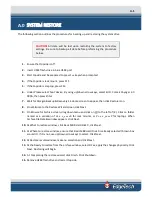
The primary objective is to ascertain which system component is at fault. First, ensure that the system is
properly installed with all connections properly mated. Next, check that the line voltages for the topside
components are within specified limits and any fuses have not blown. Fuses may fail if a wrong connection
has been made during setup. They have also been known to fail for no apparent reason. Always replace
fuses with those of the same value. If a fuse fails again within a short time, there are more serious
problems within the corresponding unit.
Open the cover of the topside electronics and check that all the cards are seated, especially if the unit has
been in transit. After checking the cards, ensure that the cable connectors are properly mated. If the
problem persists, disengage and then reengage all PC boards and do the same for all board cable
connections, before going on to any electrical testing.
All calibration adjustments are preset at the factory and should not require any modifications in the field
unless certain mechanical and/or electrical components are changed or the adjustments are inadvertently
altered.
If the above checks do not identify or remedy the problem, attempt to isolate the failure to one of the
major system components: the sonar processor, the modem/power unit, the tow vehicle, or the tow
cable. The following presents various operational problems and general comments on where to look and
what to look for.
Summary of Contents for 2000-DSS
Page 20: ......
Page 56: ...Figure 4 2 2000 Digital Telemetry Link Electronics Block Diagram...
Page 57: ...Figure 4 3 2000 Digital Telemetry Link Wiring Diagram...
Page 59: ...Figure 4 4 Tow Vehicle Electronic Block Diagram...
Page 60: ...Figure 4 5 Tow Vehicle Interconnect Drawing...
Page 63: ...Figure 4 6 Armored Cable PMI Grip Unterminated Topside...
Page 64: ...Figure 4 7 Test Cable...
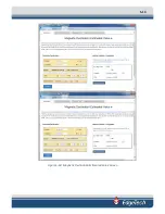
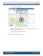
Page 77: ...5 13 Figure 5 16 Magnetic Declination Estimated Value Screen...
Page 79: ...5 15 getDeclination CR Figure 5 18...
Page 80: ......
Page 94: ......
Page 96: ......
Page 98: ......


