4-34
2050-DSS SIDE SCAN AND SUB-BOTTOM SYSTEM
0024048_REV_A
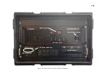
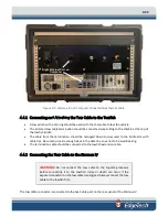
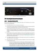
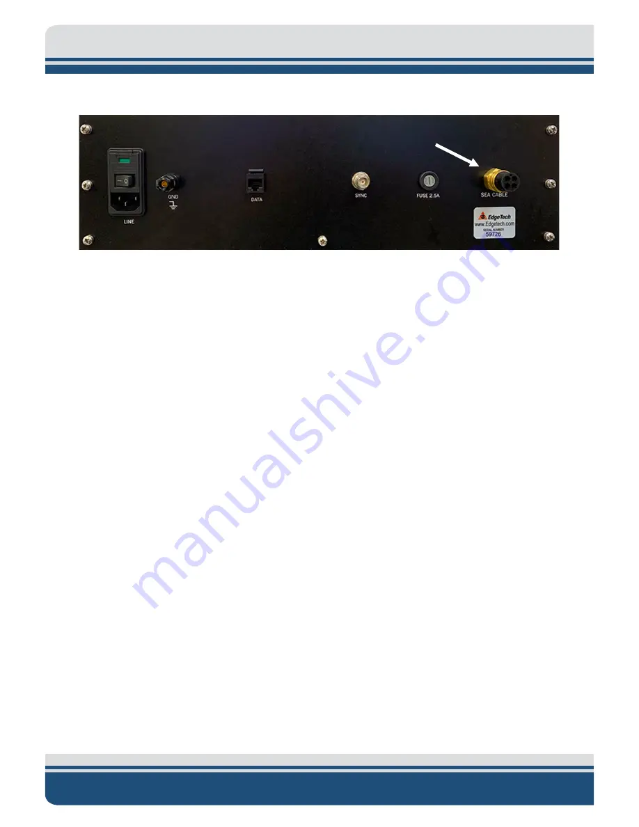
Figure 4-2: Starmux IV Sea Cable Connector
4.4.3
Connecting the Starmux IV to the Computer
4.4.3.1
Connecting to the Starmux IV DL
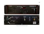
for the location of the connectors
while performing the steps below:
1.
Verify that the Starmux IV DL is not connected to AC power.
2.
Verify that the tow cable is properly connected and attached to the towfish, and then connect the
tow cable to the Sea Cable Connector on the rear panel of the Starmux IV.
3.
Connect the Ethernet patch cable to the DATA 1 Connector of the Starmux IV Digital Link and the
computer's ethernet connector. If it is an EdgeTech 2U, connect to the right-side Ethernet
Connector. Any Category 5 Ethernet patch cable can be used as long as it doesn’t exceed 100 feet
in length.
4.
Set the IP address of your computer to 192.9.0.nnn, where nnn is any integer from 1 to 100. The
factory default is an IP address of 192.9.0.101 and a port setting of 1700. Several IP addresses are
used by the system, reserved, or should not be used. See the
this manual for the IP list and details.
5.
If a navigation system will be used, connect the navigation system output to an available serial
communications port on the computer.
6.
If an external source is used to trigger the Starmux IV Digital Link, connect this source's trigger
output to the FSK connector.
•
The Starmux IV comes standard with a FSK (Frequency Shift Keyed) Trigger BNC Connector
on the rear panel, which connects with a USBL (Ultra-Short Baseline Beacon) navigation
and positioning system like the
. This provides a precise position
of the towfish, which can help make better towfish and sonar deployment and
configuration decisions. This trigger does not directly control the sonar subsystems in any
Tow Cable Connector


