background image

ix 


CUSTOMER SERVICE 

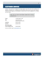
Customer service personnel at EdgeTech are always eager to hear from users of our products. Your 

feedback is welcome and is a valuable source of information that we use to improve these products. 

Therefore, we encourage you to contact EdgeTech Customer Service to offer any suggestions or to request 

technical support:  

NOTE: 

Have your system Serial Number available when contacting 

Customer Service.


E-mail:


service@edgetech.com 

Mail:


4 Little Brook Road 


West Wareham, MA 02576 

Telephone:


(508) 291-0057 

Facsimile:


(508) 291-2491 

24-Hour Emergency  

Technical Support Line: 


(508) 942-8043 

For more information, go to 

www.EdgeTech.com

. 


Summary of Contents for 6205S

Page 1: ...EdgeTech 4 Little Brook Road West Wareham MA 02576 Tel 508 291 0057 Fax 508 291 2491 www EdgeTech com 6205S BATHYMETRY SIDE SCAN SYSTEM U S E R H A R D W A R E M A N U A L 0020300_REV_E 11 6 2020...

Page 2: ...rights reserved Microsoft and Windows are registered trademarks of Microsoft Corporation Storm Case and Hardigg are trademarks of Pelican GETAC is a registered trademark of MiTAC Synnex Group HYPACK...

Page 3: ...equipment described in this manual should read and understand the warnings and cautions provided below CAUTION This equipment contains devices that are extremely sensitive to static electricity Theref...

Page 4: ...the same software drivers if applicable At times however direct replacements may not exist When this happens EdgeTech will provide the necessary drivers with the replacement part if applicable EdgeTec...

Page 5: ...tures may be periodically upgraded Therefore the information in this manual is subject to change and should be used for reference only Liability EdgeTech has made every effort to document the 6205s Ba...

Page 6: ...The items have not been misused or abused in any manner nor have repairs been attempted thereon without the approval of EDGETECH CUSTOMER SERVICE iii Written notice of the failure within the warranty...

Page 7: ...rted directly to the customer New software releases consist of the following Software enhancements that are not on the price list Software fixes and changes Product integration Documentation updates t...

Page 8: ...ied on the invoice CAUTION Never attempt to ship a Portable Topside in its Storm CaseTM alone Although rugged these cases are not intended to be used as shipping containers and the delicate internal c...

Page 9: ...erefore we encourage you to contact EdgeTech Customer Service to offer any suggestions or to request technical support NOTE Have your system Serial Number available when contacting Customer Service E...

Page 10: ...estuarine and coastal applications for over 50 years The company has responded to the scientific Naval and offshore communities needs by providing equipment such as sub bottom profilers side scan son...

Page 11: ...ncements vii RETURNED MATERIAL AUTHORIZATION viii RMA Purpose viii CUSTOMER SERVICE ix COMPANY BACKGROUND x TABLE OF CONTENTS xi LIST OF FIGURES xiv LIST OF TABLES xvii OVERVIEW 1 1 1 1 Applications 1...

Page 12: ...side Computer Requirements Specifications 3 17 3 7 Deck Cable 3 18 3 8 Mechanical Drawings 3 19 CONNECTIONS AND FORMATS 4 24 4 1 Data Formats 4 24 4 2 System Connections and Data Flow 4 25 4 2 1 Ether...

Page 13: ...for Redundant Information 8 54 8 2 1 Two Different Sensors Supplying the Same Message 8 54 8 2 2 Two Sensors Output Same Information with Different Messages 8 56 8 3 Configuring COM Ports 8 58 8 3 1...

Page 14: ...igure 3 7 6205s Array Color Codes Diagram 3 22 Figure 3 8 6205s Wiring Diagram 0019627 3 23 Figure 4 1 6205s Rack Mount Topside Interface Connections 4 26 Figure 4 2 6205s R Rack Mount Topside Interfa...

Page 15: ...g SV Data in Sonar exe 8 54 Figure 8 7 Configuration Menu 8 55 Figure 8 8 Auxiliary Sensors 8 55 Figure 8 9 Sonar Control Tab 8 56 Figure 8 10 SonarSer all ini 8 57 Figure 8 11 Sonar Remote Desktop Ap...

Page 16: ...27 TimeSyncSource Keyword Adjustments 8 74 Figure 8 28 UDP broadcast settings example 8 75 Figure 8 29 Eth1 data output 8 75 Figure 8 30 Data packets required but at 25Hz or 50Hz not 1Hz 8 76 Figure...

Page 17: ...BLES Table 3 1 Physical Specifications 3 12 Table 3 2 Acoustic Specifications 3 13 Table 3 3 Power Requirements 3 14 Table 3 4 Environmental Specifications 3 14 Table 3 5 6205s Topside Interface Speci...

Page 18: ...h frequencies The bathymetry operates at either 230kHz or 550kHz Additionally EdgeTech s latest 2205 Electronics and Modular Arrays are utilized in the 6205s resulting in an extremely lightweight desi...

Page 19: ...Hz Bathymetry Data 550 1600 kHz Dual Frequency Side Scan with 550 kHz Bathymetry Data The modular design of the 6205s allows for multi frequency bathymetry options in a single sonar head The field exc...

Page 20: ...umber of topsides CARIS HIPS SIPS supports our native JSF files for post processing For questions on Third Party Interfacing with Discover Bathymetry refer to THIRD PARTY SOFTWARE Contact EDGETECH CUS...

Page 21: ...Bathymetry Data 550 1600 kHz Dual Frequency Side Scan with 550 kHz Bathymetry Data The frequency sets listed above were chosen to provide optimum results for any given water depth up to 200m 660ft be...

Page 22: ...Sonar Head Components NOTE The terms used in Figure 2 1 are referenced throughout this manual HOUSING MOUNTING PLATE SONAR PROCESSOR SOUND VELOCITY SENSOR SVS SONAR ARRAYS PORT and STBD HOUSING SONAR...

Page 23: ...tallation and mobilization time The variable bolt pattern is shown in FIGURE 2 3 EdgeTech advises mounting the 6205s Sonar Head to the bow of a survey vessel By placing the system at the bow the sonar...

Page 24: ...built in Windows 7 Embedded PC The main firmware installed on the embedded PC is called Sonar exe which controls the sonar s hardware and performs specific functions such as signal processing and time...

Page 25: ...2 8 6205s BATHYMETRIC AND SIDE SCAN SONAR 0020300_REV_E Figure 2 4 6205s Electronics Housing and Arrays Installed...

Page 26: ...ten elements make an approximately half wavelength spaced array of sensors for its bathymetry receiver 2 1 6 Acoustic Center The individual acoustic centers of each array port and starboard converge a...

Page 27: ...2 10 Figure 2 5 Acoustic Center Location in X Y and Z and Bolt Pattern of Standard 6205s 0019604...

Page 28: ...2 11 Figure 2 6 Acoustic Center Location in X Y and Z Dimensions and Bolt Pattern with Adaptor Flange 0021206...

Page 29: ...Specifications 3 2 Acoustic Specifications SONAR HEAD MODEL 230 550 KHZ SS 230 550 BATHY 550 1600 SS 550 KHZ BATHY SIDE SCAN SONAR Center Frequency 230 520 kHz 520 1610 kHz Range per Side 225 125 m 7...

Page 30: ...quency 230 kHz 550 kHz 850 kHz 1600 kHz Horizontal Beamwidth 2 way 0 54 0 36 0 29 0 20 Range Resolution 30 mm 10 mm 9 mm 6 mm Max Range Dependent on environmental conditions absorption reverberation s...

Page 31: ...W 15 x H 7 5 Weight 5 4 kg 12 lbs 13 6 kg 30 lbs Construction Aluminum Polyethylene Polyurethane Interfaces 1 1 PPS via BNC 1 Trigger In via BNC 4 100 BaseT Ethernet Ports 3 Serial RS 232 Ports 1 1 PP...

Page 32: ...s are unidirectional however data cannot be transmitted from the 6205s to an external device All three com ports are isolated via a proprietary signal conditioning isolator board This ensures noise ge...

Page 33: ...e Discover software application for the rack mount topside sonar interface box option Minimum computer requirements are found in sub section 3 6 3 of this manual If the 6205s R Rack Mount Topside Inte...

Page 34: ...ents Specifications The topside computer must be able to run EdgeTech s Discover Bathymetric Acquisition Software and any additional third party software To do so it must include the following minimum...

Page 35: ...additional software outside the provided EdgeTech and third party bathymetric software is NOT recommended Installing software other than those supplied can have undesirable effects such as poor and or...

Page 36: ...3 19 3 8 Mechanical Drawings This section contains supporting drawings for the 6205s Swath Bathymetry and Dual Frequency Side Scan Sonar System Figure 3 4 6205s Exploded View...

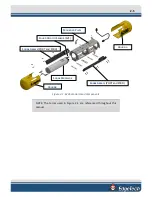
Page 37: ...3 20 Figure 3 5 6205s Exploded View with Adaptor Flange...

Page 38: ...3 21 Figure 3 6 6205s Transducer...

Page 39: ...sed on their operating frequency The color code is shown and described below Figure 3 7 6205s Array Color Codes Diagram COLOR CODES Color Code Blue 230 550SS 230 Bathy Red 230 550SS 550 Bathy Yellow 5...

Page 40: ...3 23 Figure 3 8 6205s Wiring Diagram 0019627...

Page 41: ...itch and heave data in TSS1 or EM1000 binary format minimum of 20Hz d Time sync data in NMEA format minimum of 1Hz e 1PPS TTL typically from the GNSS receiver Data may be supplied by 1 2 or 3 individu...

Page 42: ...65 ft Deck Cable The 6205s sonar interface then connects to a topside computer via a standard RJ 45 ethernet plug The correct IP addresses for the sonar head and topside computer are listed below The...

Page 43: ...ng utilized it can serve as a splitter for serial data The output ports pair with the serial ports located directly above them These ports are unidirectional 4 2 3 Hardware Connectivity FIGURE 4 1 is...

Page 44: ...itude heading roll pitch and heave data over one serial connection such as a NovaTel ProPak 6 or Applanix POS MV RS232 data output not Ethernet data output As depicted in FIGURE 4 1 the sensor is conn...

Page 45: ...4 UDP CONNECTIONS for more information on configuring 6205s for UDP data transfer FIGURE 4 2 depicts a sensor interface to the 6205s Sonar Interface that provides a time and 1PPS connection and a nav...

Page 46: ...guration Pulse per second PPS is a feature in many GPS units to provide an accurate timing signal to synchronize various devices to a precise common clock The Edgetech 6205s R rack mounted and 6205s P...

Page 47: ...ackages 4 2 4 Sonar Data Flow The Discover Bathymetric software acquisition package provides a way to control store and display the bathymetry and side scan sonar data Discover Bathymetric contains tw...

Page 48: ...nal latency to the 6205s Sonar Head via the deck cable 3 Auxiliary data is then combined with the raw sonar data and instantaneous sound velocity SV measurements They are time stamped with a common va...

Page 49: ...cy side scan data in real time The data may also be recorded as a JSF file if the user desires 6 The completed data package range angle dual frequency side scan and all auxiliary data is sent to the t...

Page 50: ...noise fluctuations on the ground line of the subsea electronics This board isolates the sensitive subsea electronics from potentially noisy grounds provided by the trigger and serial port inputs Noise...

Page 51: ...nents and inspect them Check the packing list and verify all the items on the list are included If any damage is found after unpacking the components immediately report it to the carrier and EdgeTech...

Page 52: ...5s sonar head to the bow of the survey vessel An example of an over the bow deployment is depicted in the photographs in FIGURE 5 1 If help is needed with this type of installation do not hesitate to...

Page 53: ...the images in FIGURE 5 2 If help is needed with this type of installation contact EDGETECH CUSTOMER SERVICE Figure 5 2 6205s Deployment Option 2 Over the Side 5 2 3 USV Deployment An alternative to t...

Page 54: ...build up can occur and viewing status indicators can become difficult to see due to brightness and glare The topside interface box can be set up in several ways depending on the model purchased The 6...

Page 55: ...array For instance if the Sonar Head is configured as a 230 kHz 550 kHz Side Scan with 230 kHz bathymetry and the user wants to exchange the bathymetry frequency to the 550 kHz channel then the follow...

Page 56: ...p the 6205s over so the bottom of the unit is upright to expose the remaining brackets Figure 5 6 Top Housing and Deck Cable Removed 4 Remove the 4 screws in the widest center bracket 5 Then remove th...

Page 57: ...You DO have to remove the shell from which the black pigtail comes from You DO NOT have the remove the front shell 6 Slide the shell off the housing Figure 5 8 Remove the Portion of the Shell EdgeTech...

Page 58: ...5 41 Figure 5 9 The Disconnected Bathymetry and Side Scan Sonar Cables 8 Remove all six 1 4 20 x 1 5 cap screws using the same 3 16 Allen key Figure 5 10 Remove the 6 Cap Screws...

Page 59: ...ansducer slide it away from the Housing and pull it straight out of the frame Take care not to damage the side scan and bathymetry cables out of the frame Figure 5 12 Remove the Existing Transducer 10...

Page 60: ...rently uses 12 Repeat the same steps for the opposite transducer CAUTION Each array is labeled according to the side it corresponds to Ensure the port array is installed on the port side and the starb...

Page 61: ...the supporting data if a device is not connected properly If this is the case Discover Bathymetric will display its diagnostic window and show which serial port is causing the error It is not recommen...

Page 62: ...op to Sonar application on the desktop screen If prompted for a password input admin Once logged on the Sonar Application will be displayed on the screen as shown in FIGURE 6 2 This window represents...

Page 63: ...eable on COM1 and COM2 as long as the appropriate baud rate is set in the dropdown menu next to channel assignment in Serial Port Information Window as shown in Figure 6 4 red arrow More information o...

Page 64: ...Port Information Window 4 Click on Menu File Show Status The System Status window will appear 5 At the bottom of the window click the Config bullet then the dropdown menu item named Config Item 6 Sele...

Page 65: ...FIGURE 6 5 Figure 6 5 Sensor Usage Percentage Check 7 If they are not increase the baud rates of the sensors until these percentages drop Make sure to change the baud rate accordingly in Sonar 8 When...

Page 66: ...TK Tide measurements can be incorporated into the 6205s System Most third party software packages can set up a device driver to acquire these data A 1PPS sync is needed in this case as these measureme...

Page 67: ...may degrade the 6205s system s measurements and or the sound velocity sensor at the bottom of the Sonar Head If fouling is observed clean them using a washcloth with mild soap and freshwater The SVS m...

Page 68: ...on Port 4 If this error persists longer than 30 seconds follow the procedure below to resolve the issue 1 Place the Sonar Head in water deep enough to submerge the SV probe the bottom half of the shel...

Page 69: ...d check Chan 4 on COM 4 again as in step 4 above 7 If the port reports data then proceed to normal operation If not continue to step 8 8 Closeout of Sonar exe by clicking on the X in the top right cor...

Page 70: ...Type in SET SV FORMAT 42 and press Enter Type in SET SV ZEROSUPPRESSION 5 seconds and press Enter Type in SET SVAVERAGE 4 and press Enter Type in SET SAMPLE 1 S and press Enter Type in SET DETECT 06...

Page 71: ...the same information but from different messages The following subsections describe each problem and the configuration that should be done to remedy it In the event the auxiliary sensors cannot be rep...

Page 72: ...8 55 1 Open the Auxiliary Sensors control dialog box Configuration menu Auxiliary Sensors as shown in FIGURE 8 7 and FIGURE 8 8 Figure 8 7 Configuration Menu Figure 8 8 Auxiliary Sensors...

Page 73: ...message delivers roll pitch heading and heave to the 6205s Sonar Head with no way for the particular sensor to turn off any of these specific fields If a sensor like this is paired with another senso...

Page 74: ...lated to reflect as shown in FIGURE 8 10 Figure 8 10 SonarSer all ini NOTE This new keyword disables the heading message from the OCTANS message The same can be done with an EM1000 binary format messa...

Page 75: ...de and a time source For this type of configuration only COM1 will be utilized To configure the COM ports for one sensor 1 Turn on Topside PC and connect the 6205s via the deck cable to the 6205s Tops...

Page 76: ...8 59 Figure 8 12 Finding the SonarSerial ini File Figure 8 13 SonarSerial ini File 6 Under Serial2 and Serial3 set Create 0 select File Save and close the file...

Page 77: ...y sensor information Therefore Discover will not display any errors if a sensor is not connected to COM2 or COM3 If steps 3 through 6 were not carried out then these errors would be reported in the Di...

Page 78: ...10 Check COM1 and set the correct baud rate for that device using the dropdown menu shown with a blue arrow in FIGURE 8 16 When the correct baud rate is set the State should say OK and Errors should...

Page 79: ...BATHYMETRIC AND SIDE SCAN SONAR 0020300_REV_E Figure 8 16 Checking Serial Port Information 11 Click File Show Status in the sonar window as shown circled in red in FIGURE 8 17 Figure 8 17 Checking Sen...

Page 80: ...marked by a purple box a If it is not increase the baud rate of the sensor Change the baud rate under Serial Port Information as shown in step 10 Check the Status again Otherwise the sonar will repor...

Page 81: ...s for the two sensors 1 Follow steps 1 through 6 as stated previously under appendix sub section ONE SENSOR 2 Under Serial3 set Create 0 select File Save and close the file as shown in FIGURE 8 19 CAU...

Page 82: ...green The correct data string should also be scrolling in the lower part of the window as shown in FIGURE 8 16 green arrow 7 Now Check COM2 and set the correct baud rate for the other device as done b...

Page 83: ...the link capacity to stay open It is always wise to close the Remote Desktop when finished with the configurations 8 3 3 Three Sensors Three sensors such as a gyro heading a GPS position and time sou...

Page 84: ...r Firmware by double clicking on the Sonar icon in the main Sonar Remote Desktop Screen as shown in FIGURE 8 15 designated by the green arrow 5 Now plug in the devices into COM 1 COM 2 and COM 3 The G...

Page 85: ...e button and then on the dropdown menu named Config Item as shown by the green arrow in FIGURE 8 18 11 Select Serial green arrow then click on the Update button several times blue arrow in FIGURE 8 18...

Page 86: ...8 69 Figure 8 22 Checking all COM Ports...

Page 87: ...nnections The 6205s is compatible with data sent over the Ethernet connection via UDP The SonarSerial ini is utilized to configure the system to accept these messages Note that 1PPS functionality must...

Page 88: ...anix POSVIEW software 1 Set the ethernet real time output data to groups 3 7 10 and 102 The output rate of the POSMV data should be set to 50Hz 2 The POSMV must also be set to Falling Negative Edge or...

Page 89: ...not connected to COM1 COM2 or COM3 To configure the time synchronization sources 1 Locate and open the SonarConfig ini file This file is located in the same directory as the SonarSerial ini file that...

Page 90: ...ext document CAUTION Do not alter the file in any way other than what has been specified This configuration sets the software to utilize the time and date reference received from the POSMV data string...

Page 91: ...Configuration The 6205s is compatible with the Ekinox Apogee systems from SBG Systems Follow the below steps to configure the 6205s and the SBG for communication over the Ethernet interface via UDP R...

Page 92: ...8 75 Figure 8 28 UDP broadcast settings example Figure 8 29 Eth1 data output...

Page 93: ...8 76 6205s BATHYMETRIC AND SIDE SCAN SONAR 0020300_REV_E Figure 8 30 Data packets required but at 25Hz or 50Hz not 1Hz...

Page 94: ...8 77 Figure 8 31 1PPS settings example Falling Edge and 1msec duration...

Page 95: ...up down arrow keys select EUFI Corsair Voyager 3 0 000A then press Enter 5 Wait for Paragon Backup Recovery 14 Home screen to appear then click Restore icon 6 On Welcome to the Restore Wizard screen c...

Page 96: ...Party topsides contact EDGETECH CUSTOMER SERVICE A 2 1 HYPACK The processed bathymetry and side scan data are sent in real time to the HYPACK HYSWEEP survey applications These applications display and...

Page 97: ...n July 2014 supports EdgeTech s bathymetry and side scan data formats For more information on CARIS visit http www caris com A 2 5 EIVA NaviSuite EIVA s NaviSuite constitutes a complete advanced multi...

Reviews: