background image


3-8 


Figure 3-3: 701 DL With Computer Rear Panel 

SEA CABLE connector 

ETHERNET connector 

Video Card 

POWER switch 

VAC INPUT connector 

COM 1-NAV connector 

USB connectors 

ETHERNET connector 

SYNC connector 

VAC INPUT connector 

POWER switch 

Summary of Contents for 701 DIGITAL LINK

Page 1: ...EdgeTech 4 Little Brook Road West Wareham MA 02576 Tel 508 291 0057 Fax 508 291 2491 www EdgeTech com 701 DIGITAL LINK U S E R H A R D W A R E M A N U A L 0004809_REV_ F 4 28 2020 ...

Page 2: ...ey are issued in strict confidence on condition that they not be copied reprinted or disclosed to a Third Party either wholly or in part without the prior written consent of EdgeTech Any reproduction of EdgeTech supplied software or file sharing is strictly prohibited Copyright 2020 EdgeTech All rights reserved ...

Page 3: ...s for personnel WARNING High Voltage may be present in all parts of the system Therefore use caution when the electronics are removed from their containers for servicing CAUTION Operation with improper line voltage may cause serious damage to the equipment Always ensure that the proper line voltage is used Warnings Cautions and Notes Where applicable warnings cautions and notes are provided in thi...

Page 4: ...re drivers if applicable At times however direct replacements may not exist When this happens EdgeTech will provide the necessary drivers with the replacement part if applicable EdgeTech may also change certain hardware per customer requirements Therefore portions of this manual such as parts lists and test features are subject to change These sections should be used for reference only When change...

Page 5: ...EdgeTech s 701 Digital Link Although this manual encompasses the latest operational features of the 701 Digital Link some features may be periodically upgraded Therefore the information in this manual is subject to change and should be used for reference only Liability EdgeTech has made every effort to document the 701 Digital Link in this manual accurately and completely However EdgeTech assumes ...

Page 6: ...thereon without the approval of EdgeTech Customer Service iii Written notice of the failure within the warranty period is forwarded to Seller and the directions received for properly identifying items returned under warranty are followed iv The return notice authorizes Seller to examine and disassemble returned products to the extent Seller deems necessary to ascertain the cause for failure The wa...

Page 7: ...ctly to the customer New software releases consist of the following Software enhancements that are not on the price list Software fixes and changes Product integration Documentation updates to on line help Tests for compatibility with other modules Software patches consist of software that has undergone the following Minor software enhancements Software fixes and changes EdgeTech customers are ent...

Page 8: ...voice CAUTION Never attempt to ship a Portable Topside in its Storm CaseTM alone Although rugged these cases are not intended to be used as shipping containers and the delicate internal components could be damaged Shipping in this manner will void any warranties NOTE All shipping charges shall be the responsibility of the customer unless under warranty as EdgeTech will pay for return shipping NOTE...

Page 9: ...re we encourage you to contact EdgeTech Customer Service to offer any suggestions or to request technical support NOTE Please have your system Model and Serial Number available when contacting Customer Service E mail service edgetech com Mail 4 Little Brook Road West Wareham MA 02576 Telephone 508 291 0057 Facsimile 508 291 2491 24 Hour Emergency Technical Support Line 508 942 8043 For more inform...

Page 10: ...tuarine and coastal applications for over 50 years EdgeTech responds to the needs of the Scientific Naval and Offshore communities by providing industry leading equipment such as Sub Bottom Profilers Side Scan Sonar Acoustic Releases USBL Positioning Systems and Bathymetric Systems that have become standards in the industry EdgeTech consistently anticipates and responds to future needs with an act...

Page 11: ... CUSTOMER SERVICE ix COMPANY BACKGROUND x TABLE OF CONTENTS xi LIST OF FIGURES xiii LIST OF TABLES xiv 1 0 OVERVIEW 1 1 1 1 Applications 1 1 2 0 SPECIFICATIONS 2 2 3 0 SETUP AND ACTIVATION 3 1 3 1 Unpacking and Inspection 3 1 3 2 Installing the 701 DL 3 1 3 2 1 Connecting the 701 DL 3 2 3 2 1 1 Connecting to the 701 DL 3 2 3 2 1 2 Connecting to the 701 DL With Computer 3 3 3 2 2 701 DL Controls In...

Page 12: ... 0 MAINTENANCE 4 1 5 0 TROUBLESHOOTING 5 1 5 1 701 DL Digital Link Troubleshooting Guide 5 1 5 2 701 DL with 2U Computer Troubleshooting Guide 5 2 5 3 Part Numbers for Major Components 5 2 A 0 COMPUTER SYSTEM RESTORE A 1 B 0 PRINTERS B 1 ...

Page 13: ...xiii LIST OF FIGURES Figure 3 1 701 DL Front and Back Panels 3 5 Figure 3 2 701 With Computer Front Panel 3 7 Figure 3 3 701 DL With Computer Rear Panel 3 8 ...

Page 14: ...701 DL Specifications 2 3 Table 3 1 701 DL Controls Indicators and Connections 3 4 Table 3 2 701 DL With Computer Controls Indicators and Connections 3 6 Table 5 1 701 DL Digital Link Troubleshooting Guide 5 1 Table 5 2 701 DL Rackmount Troubleshooting Chart 5 2 ...

Page 15: ... and ADSL modem A Sync Trigger port provides an interface with an external TTL trigger EdgeTech Discover software interfaces with the 701 DL monitors and controls the attached towfish and displays and records acquired sonar and sensor data The 701 DL fits a 19 inch rack and is delivered mounted independently in a rugged 2U SKB case or mounted with an EdgeTech provided computer in a rugged 6U case ...

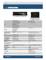
Page 16: ...on Sealed high impact polyurethane case Shipping Container Size 61 cm 24 in high 61 cm 24 in wide 30 5 cm 12 in deep 71 1 cm 28 in high 66 0 cm 26 in wide 50 8 cm 20 in deep Shipping Weight 11 3 Kg 25 lb 47 7 kg 105 lb Operating Temp 0 45 C 32 113 F 0 45 C 32 113 F Storage Temp 10 60 C 14 140 F 10 60 C 14 140 F Operating relative humidity 5 90 non condensing 5 90 non condensing Non operating stora...

Page 17: ...ard High impact industrial keyboard Pointing device High impact industrial trackball External trigger I O ports 1 Ethernet 1 Trigger 1 Ethernet 3 RS 232 6 USB 2 2 USB 3 1 Trigger Table 2 1 701 DL Specifications ...

Page 18: ...missing immediately contact EDGETECH CUSTOMER SERVICE Do not install or operate any equipment that appears to be damaged After unpacking the system components store the shipping containers including any packing materials in a safe place for later use When transporting or storing the system pack all items in their original shipping containers in the same way they were originally shipped Store the s...

Page 19: ...performing the steps below 1 Verify that the 701 DL is not connected to AC power 2 Verify that the tow cable is properly connected and attached to the towfish and then connect the tow cable to the SEA CABLE connector 3 Connect the Ethernet patch cable to the DATA connector of the 701 DL Digital Link and to the Ethernet connector of the computer 2U Getac Semirugged laptop or user supplied This cabl...

Page 20: ...he LCD monitor and the AC power source At this point perform any pre deployment checks as prescribed by the towfish hardware manual such as a rub test Operation instructions for the topside and towfish can also be found in the supplied user manuals 3 2 2 701 DL Controls Indicators and Connections The 701 DL s digital link controls indicators and connections are described below FRONT PANEL Power Sw...

Page 21: ...g to the external topside processor Sync Connector It provides an input connection for a TTL external trigger that is sent to the towfish Sea Cable Connector SubConn MCBH4F female connector to sea cable going out to tow vehicle Table 3 1 701 DL Controls Indicators and Connections ...

Page 22: ...Front and Back Panels SYNC connector LINE VAC connector Switch and AC Fuse DATA connector LAN LINK FISH POWER and POWER indicators POWER Switch SEA CABLE connector Grounding Lug Data Connector Sea Cable Connector VAC Connector Power Switch Fuse ...

Page 23: ...or RJ 45 Standard Ethernet connection for connecting to the external topside processor Sync Connector It provides an input connection for a TTL external trigger that is sent to the towfish Sea Cable Connector SubConn MCBH4F female connector to sea cable going out to tow vehicle Grounding Lug Grounding Lug FRONT PANEL COMPUTER USB Connectors 2 USB connectors Four on the back panel and two on the fr...

Page 24: ...3 7 Figure 3 2 701 With Computer Front Panel FISH POWER indicator SYSTEM POWER indicator POWER switch DVD drive USB connectors LINK indicator LAN indicator ...

Page 25: ...701 DL With Computer Rear Panel SEA CABLE connector ETHERNET connector Video Card POWER switch VAC INPUT connector COM 1 NAV connector USB connectors ETHERNET connector SYNC connector VAC INPUT connector POWER switch ...

Page 26: ...ould flash continuously and the LINK indicator should flash while a reliable communications link with the towfish is being established and then illuminate continuously when the link is found Also the NET Radio Indicator Tab in the lower control panel of the Discover application UI should display 3 4 Post Recovery After recovering a tow vehicle from a survey power down the topside computer and 701 ...

Page 27: ...es little maintenance However to ensure long lasting reliable service some periodic maintenance is recommended Maintenance of the system should be performed regularly or as often as necessary depending on use However most of the maintenance is performed after each deployment and recovery cycle ...

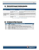
Page 28: ... fuse is good 5 amp Fuses on the rear panel of topside ac connection bad Check fuses for continuity Replace if necessary The indicator is not operating Open the topside processor and check the indicator and wiring The Green LAN indicator on the topside does not illuminate when the unit is turned on There is no connection between the topside and the computer Check LAN connections between topside an...

Page 29: ...nnected to AC power Check the AC power source The indicator is not operating Open topside processor and check indicator and wiring Table 5 2 701 DL Rackmount Troubleshooting Chart 5 3 Part Numbers for Major Components 0003117 ASSY TOP KIT SPARES 701 DL DIGITAL LINK Part MTL Description Qty 10 0012635 ASSY SUB MODEM 701 D LINK DSL 1 30 0011860 PCB ASY TOP POWER SUPPLY ANALOG POWER BOARD 4200 P 566 ...

Page 30: ...ore icon 6 On Welcome to the Restore Wizard screen click Next Browse for Archive and click the specific image the file ending with the extension pbf When the Archive File Details window appears click Next 7 At What to restore window click Basic MBR Hard Disk 0 click Next 8 At Where to restore window ensure that Basic MBR Hard Disk 0 is already selected brown box around it If it is not use up down ...

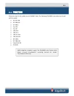
Page 31: ...k well with the system EPC HSP 100 EPC 1086 NT EPC 9206 iSys V8 5 iSys v12 Ultra 200 Ultra 120 Ultra 120 HD Ultra 200 HD EPC 1086 EPC 1086 Old Geoprinter 975 TDU 850 NOTE EdgeTech Topsides support the ETHERNET only Printers listed above Consult manufacturer s operating manual for printer requirements and set up ...

Reviews: