6400LF Converged Network Appliance Installation Guide
8
F
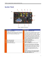
System Status LED
L
Video Connector
NOTE:
If a monitor is connected to the
control panel video connector, the rear video
port on the server board will be disabled and
the control panel video will be enabled. The
video source is the same for both connectors
and is switched between the two, with the
control panel having priority over the rear
video. This provides for easy front
accessibility to the server.
Back Panel
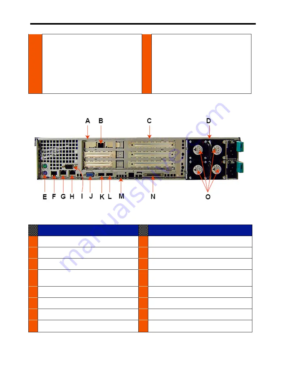
Figure 3: 6400LF Back Panel
Description
Description
A
Low Profile PCI Add-in Card Slots
H
NIC #2 Connector
B
Management NIC
I
DB9 Serial A Port Cut-out
C
Full Height PCI Add-in Slots
J
Video Connector
D
Power Supply Modules (1+1 Configuration
Shown)
K
USB 1 Connector
E
PS2 Keyboard and Mouse Ports
L
USB 2 Connector
F
RJ45 Serial B Port
M
Diagnostic Post Code LEDs
G
NIC #1 Connector
N
External SCSI Channel B Connector
O
Non-redundant Power Module Fans


