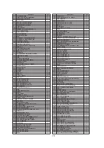


ENGLISH
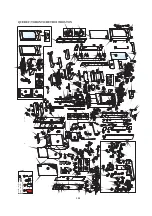
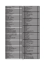
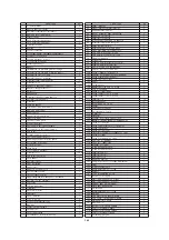
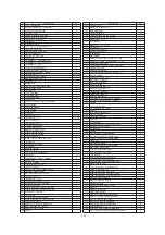
pz.
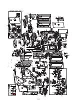
1
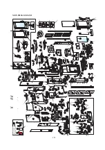
Anti-vibration mounts
4
2
Cast iron base with bracket
1
3
Internal inspection cap
1
4
Front refractory housing
2
5
Ash pan
1
6
Rear refractory housing
1
7
Rear refractory front
1
8
Burner gasket
1
9
Burner
1
10
Relief plate
1
11
T.T.B internal hexag screw M4 x 12
2
12
Nut with M6 wings
2
13
Combustion chamber cleaning plate
1
14
Secondary feed screw
1
15
Spark plug bushing
1
16
Spark plug
1
17
Turbulator 1st turn first row
3
18
Turbulator 1st turn second row
3
19
Turbolatore 2° giro
4
20
Cleaning block assembly
1
22
Boiler inspection gasket
2
23
Gasket Ø 13
L=1,5 mt
24
Upper welded boiler
1
25
1/2" Air relief tap
1
26
1/2" Well
1
27
Manometer
1
28
Smoke pipe boiler gasket
1
29
Smoke pipe assembly
1
30
Gasket
1
31
Smoke outlet spiral
1
32
Smoke extraction fan
1
33
Sensor holder cap
1
34
Smoke sensor
1
36
Upper front panel support
1
37
Pellet cover
1
38
Pellet pan hinge
2
39
Upper plate
1
40
Right red sheet metal side Ottawa
1
41
Left red sheet metal side Ottawa
1
43
Sheet metal top
1
44
Door Scamolex
1
45
Scamolex door stop
2
46
Right lower rear panel
1
47
Door lock
1
48
Door pin
1
49
Cold hand
1
50
Lever for cleaning
1
51
Gasket Ø 13
L=2,0 mt
52
Front top sheet
1
53
Welded door
1
54
Spy hole assembly
1
55
Vent tube
2
56
Faux glass
1
57
Elastic washer D.10
1
58
Right galvanised side
1
59
Left galvanised side
1
60
Boiler inspection plate with relief
2
61
Assembled front panel assembly
1
62
Flat cable
1
63
Mimic panel
1
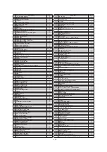
68
Gasket
1
69
Burner spacer
1
70
Bearing
1
71
Bearing holder
1
72
Screw T.E. 4x 35
4
73
Gear motor stop bracket
1
74
Pad
4
75
Gearmotor Ottawa
2
76
Pellet pipe
1
77
Pipe clamp
1
78
Safety thermostat R/Aut 150°
1
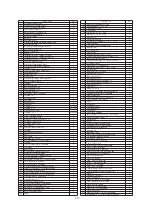
ENGLISH
pz.
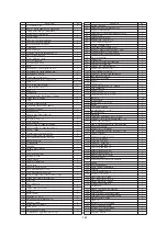
79
Loading device body
1
80
Gearmotor locking bush
1
81
Gear motor support
1
82
Teflon bush for feed screw
2
83
Feed screw assembly
1
84
Feed screw gasket
1
85
Feed screw half-shell closing
1
86
Upper feeder closing
1
87
Pellet hopper body
1
88
Rear pellet hopper wall
1
89
Pellet hopper protection grille
1
90
Right rear hopper side
1
91
Left rear hopper side
1
94
Vacuum gauge plate
1
95
Vacuum gauge
1
96
Left lower rear panel
1
97
Holder rear panel
1
98
Plug with switch
1
99
Serial port whit flat cable
1
100
Boiler relief pipe
1
101 Automatic air relief valve
1
102
boiler connection pipe
1
103
Return connection pipe
1
104
Sensor
1
105
Pipe to tank
1
106
3/8" white air relief tap
1
107
Expansion tank
1
109
Inlet pipe
1
110
Flexible pipe 3/4 F-F L=500
1
111
Flexible pipe 3/4 F-F L=220
2
112
Gasket 3/4
14
113
Hydraulic kit
1
114
Brass reducer 1"F a 3/4" M
1
115
Pump
1
116
Hydraulic casing kit
1
117
3-way Solenoid Valve
1
118
Exchanger
1
119
Flow switch
1
120
Safety valve 3 bar 1/2" Male-Female
1
121
Boiler relief valve with bolt 1/2" Male
1
122
Pipe to exchanger
1
123
Primary return pipe from exchanger
1
124
Hot water pipe
1
125
Pipe from circulator
1
126
Primary fluid pipe from 3-way valve
1
127
Return pipe
1
128
Pipe to the 3-way valve
1
129
Electronic detector
1
130
cable with connector
1
131
Retaining valve
1
132
Pipe fastening nut 3/4"
3
133
Pipe fastening nut 1/2"
3
134
1" pump gasket
1
135
1/2" pipe gasket
6
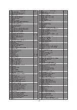
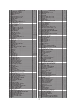
139
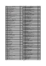
Door with glass
1
140
Burner assembly
1
141
Pellet feeder with primary feed screw
1
143
Glove
1
144
Desiccant crystals
1
145
Radio control with display
1
146
Scraper
1
147
Mains cable
1
148
Kit of electrical cables
1
149
Top thermal protection
1
150
Boiler thermal protection
1
151 Antenna for radio control
1
156
Profile for microswitch
1
157
Microswitch
1
159
Remote control with display
1
160
Ceiling
1
161
Right red sheet metal side Atlanta
1
162
Left red sheet metal side Atlanta
1
164
Gearmotor Atlanta
2
167
Stopper 3/8"
1
168
Kit of electrical cables Atlanta
1
169
Electronic circuit board Atlanta
1
170
Kit of electrical cables Ottawa
1
171
Electronic circuit board Ottawa
1
172
Handle locking
1
167
Summary of Contents for Atlanta
Page 24: ...24 ITALIANO MANUTENZIONE 2 fig A 3 1 fig B fig C fig D 4 3 4 3 2 4 fig E fig F fig G ...
Page 50: ...ENGLISH 50 MAINTENANCE 2 fig A 3 1 fig B fig C fig D 4 3 4 3 2 4 fig E fig F fig G ...
Page 76: ...76 FRANÇAIS ENTRETIEN 2 fig A 3 1 fig B fig C fig D 4 3 4 3 2 4 fig E fig F fig G ...
Page 102: ...102 ESPAÑOL MANUTENCIÓN 2 fig A 3 1 fig B fig C fig D 4 3 4 3 2 4 fig E fig F fig G ...
Page 128: ...128 DEUTSCH WARTUNG 2 Abb A 3 1 Abb B Abb C Abb D 4 3 4 3 2 4 Abb E Abb F Abb G ...
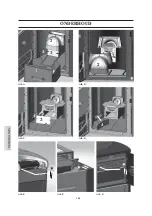
Page 154: ...154 NEDERLANDS ONDERHOUD Afb A Afb B Afb C Afb D 3 4 3 2 4 Afb E Afb F Afb G 2 3 1 4 ...
Page 179: ...664550 03 14 L w w w e d i l k a m i n c o m ...