
ENGLISH
36
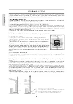
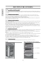
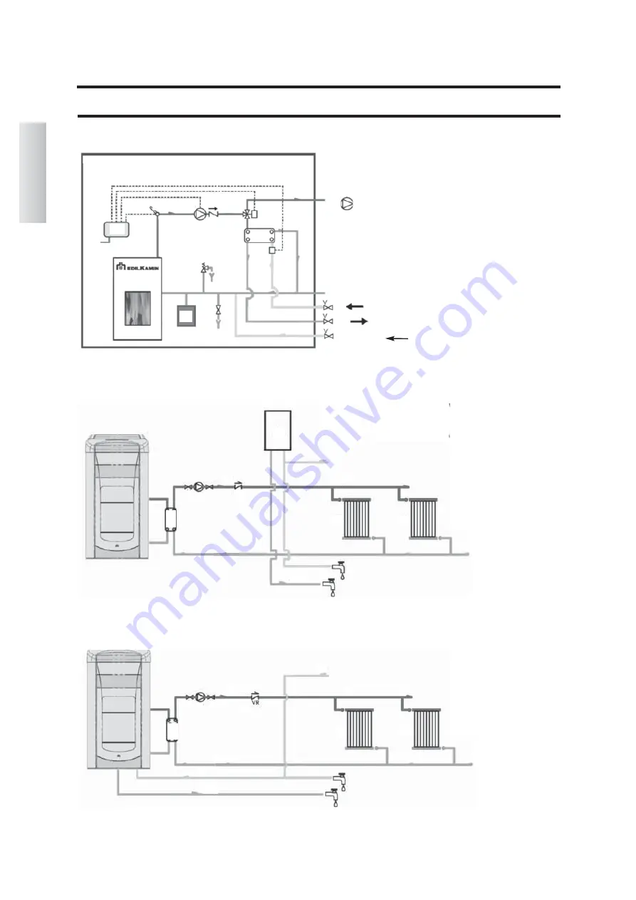
HYDRAULIC CONNECTIONS
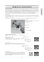
Hydraulic schematic diagram of built in kit.
The following are some schematic diagrams indicative of possible systems.
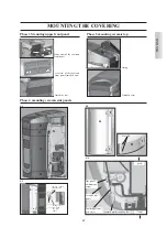
Heating system combined with boilers.
KEY
ACS:
Domestic Hot Water
AF:
Cold Water
MI:
System delivery
P:
pump (circulator)
Ra:
Radiators
RI:
System Return
Sc 30:
30 Plate Exchanger
V:
Valve
VR:
Non-return valve
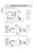
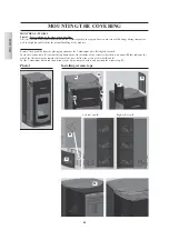
Heating system with single source of heat for the production of heat and domestic hot water
KEY
ACS:
Domestic Hot Water
AF:
Cold Water
MI:
System delivery
EV:
3 way Solenoid valve
F:
Flow meter
P:
Pump (circulator)
Po:
Pump OPTIONAL
RE:
Electronic Regulator
RI:
System Return
S:
Drainage
Sc:
Exchanger
ST:
Temperature Probe
V:
Valve
VE:
Expansion tank
VR:
Check Valve
VSP:
Safety valve
VST:
Thermal discharge valve
AF
MI
RI
VR
P
Sc
30
V
ACS
V
MI
RI
RA
RA
AF
F
AF
EV
MI
RI
VSP
ACS
VR
ST
P
Sc
RE
Power
V
S
VE
AF
ACS
AF
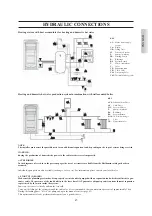
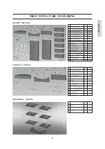
Refilling
heating system
KEY
ACS:
Domestic Hot Water
AF:
Cold Water
MI:
System delivery
P:
pump (circulator)
Ra:
Radiators
RI:
System Return
SB:
boiler
Sc 30:
30 Plate Exchanger
V:
Valve
VR:
Non-return valve
AF
MI
RI
VR
SB
P
Sc
30
V
ACS
V
MI
RI
RA
RA
Po
Summary of Contents for Atlanta
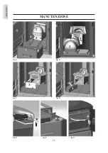
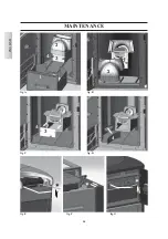
Page 24: ...24 ITALIANO MANUTENZIONE 2 fig A 3 1 fig B fig C fig D 4 3 4 3 2 4 fig E fig F fig G ...
Page 50: ...ENGLISH 50 MAINTENANCE 2 fig A 3 1 fig B fig C fig D 4 3 4 3 2 4 fig E fig F fig G ...
Page 76: ...76 FRANÇAIS ENTRETIEN 2 fig A 3 1 fig B fig C fig D 4 3 4 3 2 4 fig E fig F fig G ...
Page 102: ...102 ESPAÑOL MANUTENCIÓN 2 fig A 3 1 fig B fig C fig D 4 3 4 3 2 4 fig E fig F fig G ...
Page 128: ...128 DEUTSCH WARTUNG 2 Abb A 3 1 Abb B Abb C Abb D 4 3 4 3 2 4 Abb E Abb F Abb G ...
Page 154: ...154 NEDERLANDS ONDERHOUD Afb A Afb B Afb C Afb D 3 4 3 2 4 Afb E Afb F Afb G 2 3 1 4 ...
Page 179: ...664550 03 14 L w w w e d i l k a m i n c o m ...


