


62
FRANÇAIS
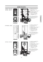
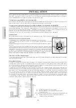
BRANCHEMENTS HYDRAULIQUES
Schéma hydraulique du kit intégré.
Ci-dessous sont indiqués quelques schémas d'installation possible à titre indicatif.
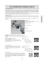
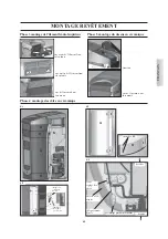
Installation pour chauffage combiné au chauffe-eau.
LÉGENDE
ACS:
Eau Chaude Sanitaire
AF:
Eau Froide
MI:
Refoulement Installation
P:
Pompe (circulateur)
Ra:
Radiateurs
RI:
Retour Installation
Sc 30:
Échangeur 30 plaques
V:
Soupape
VR:
Soupape antiretour
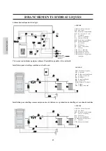
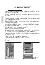
Installation pour chauffage comme unique source de chaleur, avec production de chauffage et eau chaude sanitaire
LÉGENDE
ACS:
Eau Chaude Sanitaire
AF:
Eau Froide
MI:
Refoulement Installation
EV:
Électrovanne à 3 voies
F:
Flussostat
P:
Pompe (circulateur)
Po:
Pompe OPTIONS
RE:
Régulateur électronique
RI:
Retour Installation
S:
Évacuation
Sc:
Échangeur
ST:
Sonde Température
V:
Soupape
VE:
Vase d'expansion
VR:
Soupape antiretour
VSP:
Soupape de sécurité
VST:
Soupape d'échappement
thermique
AF
MI
RI
VR
P
Sc
30
V
ACS
V
MI
RI
RA
RA
AF
F
AF
EV
MI
RI
VSP
ACS
VR
ST
P
Sc
RE
Réseau
V
S
VE
AF
ACS
AF
Réintégration
installation de
chauffage
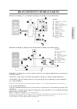
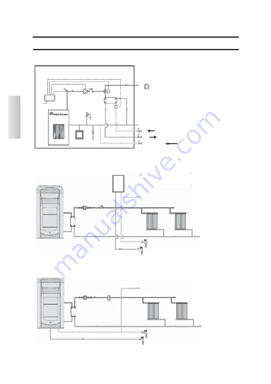
LÉGENDE
ACS:
Eau Chaude Sanitaire
AF:
Eau Froide
MI:
Refoulement Installation
P:
Pompe (circulateur)
Ra:
Radiateurs
RI:
Retour Installation
SB:
Chauffe-eau
Sc 30:
Échangeur 30 plaques
V:
Soupape
VR:
Soupape antiretour
AF
MI
RI
VR
SB
P
Sc
30
V
ACS
V
MI
RI
RA
RA
Po
Summary of Contents for Atlanta
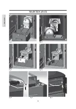
Page 24: ...24 ITALIANO MANUTENZIONE 2 fig A 3 1 fig B fig C fig D 4 3 4 3 2 4 fig E fig F fig G ...
Page 50: ...ENGLISH 50 MAINTENANCE 2 fig A 3 1 fig B fig C fig D 4 3 4 3 2 4 fig E fig F fig G ...
Page 76: ...76 FRANÇAIS ENTRETIEN 2 fig A 3 1 fig B fig C fig D 4 3 4 3 2 4 fig E fig F fig G ...
Page 102: ...102 ESPAÑOL MANUTENCIÓN 2 fig A 3 1 fig B fig C fig D 4 3 4 3 2 4 fig E fig F fig G ...
Page 128: ...128 DEUTSCH WARTUNG 2 Abb A 3 1 Abb B Abb C Abb D 4 3 4 3 2 4 Abb E Abb F Abb G ...
Page 154: ...154 NEDERLANDS ONDERHOUD Afb A Afb B Afb C Afb D 3 4 3 2 4 Afb E Afb F Afb G 2 3 1 4 ...
Page 179: ...664550 03 14 L w w w e d i l k a m i n c o m ...


