background image

22 

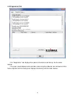
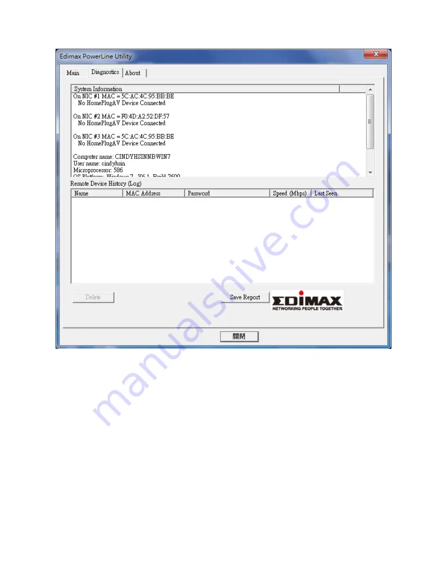
4.2 Diagnostics Tab 


The “Diagnostics” tab displays the system information and history of all remote 

devices. 

The upper panel displays technical data concerning the software and hardware on the 

host computer and the lower panel displays the history of all remote devices. 


Summary of Contents for HP-5102Wn

Page 1: ...HP 5102Wn User Manual 12 2014 v1 0...

Page 2: ...ght to revise this publication and to make changes from time to time in the contents hereof without the obligation to notify any person of such revision or changes The product you have purchased and t...

Page 3: ...N 10 III 1 Setup Wizard 12 III 2 Device Configuration 13 III 3 WLAN Configuration 14 III 4 Status Overview 16 III 5 Management 17 III 5 1 Account 18 III 5 2 DHCP Server 19 III 5 3 Factory Restore 20 I...

Page 4: ...I 1 Package Contents Before you start using this product please check if there is anything missing in the package and contact your dealer to claim the missing items s HP 5102Wn Ethernet Cable CD ROM Q...

Page 5: ...s to connect with another Powerline adapter Press for 5 8 seconds to leave an encrypted powerline network group 3 WPS Button Press for 10 seconds to reset the Wi Fi functions web U I settings to facto...

Page 6: ...owerline traffic excellent connection Off No Powerline connection detected Orange Flashing Powerline traffic good connection Red Flashing Powerline connection bad connection LAN Green On LAN port conn...

Page 7: ...can reset the device back to its factory default settings To reset Powerline settings press and hold the Reset Group button for at least 10 seconds The power LED will display on when the HP 5102Wn is...

Page 8: ...ce contains small parts which are a danger to small children under 3 years old Please keep the powerline adapter out of reach of children 6 Do not place the powerline adapter on paper cloth or other f...

Page 9: ...in the same room and then relocate the HP 5102Wn to its preferred location after setup is complete II 1 Installation 1 Connect a Powerline adapter to your router via Ethernet cable and plug it into a...

Page 10: ...5 To connect to your HP 5102Wn s Wi Fi use a Wi Fi device e g computer tablet smartphone to search for a Wi Fi network with the SSID EdimaxPLC_ and connect to it The password is displayed on the prod...

Page 11: ...port on the underside of the product II 2 Leaving a Powerline Network Press the Reset Group button on the powerline adapter for 5 8 seconds to leave a Powerline network that the HP 5102Wn is connected...

Page 12: ...ss the WPS button on the HP 5102Wn for less than 2 seconds to activate WPS The HP 5102Wn s Wi Fi LED will display on to indicate that WPS is active 2 Within two minutes press the WPS button on your wi...

Page 13: ...ress the HP 5102Wn must be disconnected from your router If using a dynamic IP or if you later set your powerline adapter to use a static IP address then you do not need to disconnect the HP 5102Wn fr...

Page 14: ...puter s IP address is in the same subnet 3 Go to 192 168 2 2 in a web browser and you will arrive at the login screen as shown below The default username is admin and the default password is 1234 Note...

Page 15: ...set the SSID and password of the powerline adapter Name SSID Enter the network name SSID name for the Wi Fi network The SSID can consist of any combination of up to 32 alphanumeric characters Password...

Page 16: ...s settings to find your powerline adapter s IP address Fixed IP IP Address Specify a static IP address here This IP address will be assigned to your powerline adapter and will replace the default IP a...

Page 17: ...relessly cannot be read by anyone who does not know the correct encryption key By default WPA encryption is enabled It s essential to configure wireless security in order to prevent unauthorised acces...

Page 18: ...hannels 1 13 approved for use in other countries Security Settings Open Authentication is disabled and no password key is required to connect to the powerline adapter Not recommended WEP WEP Wired Equ...

Page 19: ...16 III 4 Status Overview Displays the current firmware version and the MAC address of any wireless clients which are connected to the powerline adapter...

Page 20: ...17 III 5 Management The sub menu provides access to various management settings...

Page 21: ...ount Account settings are the username and password used to log in to the control panel The default values are username admin password 1234 It is recommended to change account settings according to yo...

Page 22: ...network devices connected to the powerline adapter You can specify a range of IP address to assign Do not enable DHCP server is your router has also enabled DHCP server First IP Address Enter the sta...

Page 23: ...20 III 5 3 Factory Restore You can restore the powerline adapter back its factory default state This resets all settings including SSID password and IP settings...

Page 24: ...our Wi Fi or use the auto setting Selecting a less crowded channel can improve performance due to less interference from other Wi Fi devices See below for information about country specific restrictio...

Page 25: ...22 Channel Width Select wireless channel width bandwidth used by wireless signals from the device the recommended value is HT20 40...

Page 26: ...utility software please uninstall any existing Powerline utility software you may already have To install the utility software insert the CD into your CD ROM drive and the setup wizard should begin au...

Page 27: ...the functions of each tab within the Powerline utility software IV 1 1 Main The Main tab provides a list of Powerline adapters connected to the network Use the drop down menu to select a network card...

Page 28: ...the correct password this column will show the password To set the password of the adapter first select the adapter by clicking on its name and then click Enter Password button A dialog box will appe...

Page 29: ...ow Set All Remote Devices Whose Password Has Been Entered Change the network name of all devices that appear in box above whose password has been entered Set Local Devices Change the network name for...

Page 30: ...27 IV 1 3 About The About tab displays basic information about the software...

Page 31: ...it should be located in the lower left corner of your computer then click Control Panel Double click the Network and Internet Connections icon click Network Connections and then double click Local Ar...

Page 32: ...s then click Manage Network Connections Right click Local Area Network then select Properties The Local Area Connection Properties window will then appear select Internet Protocol Version 4 TCP IPv4 a...

Page 33: ...30 V 3 Windows 7 1 Click the Start button it should be located in the lower left corner of your computer then click Control Panel 2 Under Network and Internet click View network status and tasks...

Page 34: ...31 3 Click Local Area Connection 4 Click Properties...

Page 35: ...t Use the following IP address then input the following values IP address 192 168 2 10 Subnet Mask 255 255 255 0 Click OK when finished V 4 Windows 8 8 1 1 From the Windows 8 Start screen you need to...

Page 36: ...33 2 In desktop mode click the File Explorer icon in the bottom left of the screen as shown below...

Page 37: ...34 3 Right click Network and then select Properties 4 In the window that opens select Change adapter settings from the left side...

Page 38: ...35 5 Choose your connection and right click then select Properties 6 Select Internet Protocol Version 4 TCP IPv4 and then click Properties...

Page 39: ...Click OK when finished V 5 Mac OS 1 Have your Macintosh computer operate as usual and click on System Preferences 2 In System Preferences click on Network 3 Here you will see all of your network conn...

Page 40: ...t panel From the drop down menu select Manually 5 In the panel on the right side enter IP address 192 168 2 10 and subnet mask 255 255 255 0 Click on Apply 6 In the left sidebar Ethernet should now di...

Page 41: ...d by the computers on your home network is the location of the DNS server your ISP has assigned to you DSL Modem DSL stands for Digital Subscriber Line A DSL modem uses your existing phone lines to tr...

Page 42: ...rovides connectivity to the Internet for individuals and other businesses or organizations LAN Local Area Network A LAN is a group of computers and devices connected together in a relatively small are...

Page 43: ...gned by InterNIC TCP IP UDP Transmission Control Protocol Internet Protocol TCP IP and Unreliable Datagram Protocol UDP TCP IP is the standard protocol for data transmission over the Internet Both TCP...

Page 44: ...s with FCC radiation exposure set forth for an uncontrolled environment In order to avoid the possibility of exceeding the FCC radio frequency exposure limits human proximity to the antenna shall not...

Page 45: ...Voraussetzungen gem den Richtlinien 1999 5 EC 2009 125 EC 2006 95 EC 2011 65 EC Spanish El presente equipo cumple los requisitos esenciales de la Directiva 1999 5 EC 2009 125 EC 2006 95 EC 2011 65 EC...

Page 46: ...EN 301 489 17 V2 1 1 2009 Recommendation 99 519 EC EMF EN 62311 2008 Directives 2004 108 EC EMC EN 55022 2010 CISPR I 257 CD 2008 EN 61000 3 2 2006 A2 2009 EN 61000 3 3 2008 EN 50412 2 1 2005 IEC 610...

Page 47: ...44...

Page 48: ...HP 5102AC User Manual 02 2013 v1 0...

Page 49: ...its distributor or its dealer assumes the entire cost of all necessary servicing repair and any incidental or consequential damages resulting from any defect in the software Edimax Technology Co Ltd...

Page 50: ...terface 6 2 3 Fast Ethernet Port 6 Chapter 3 Utility Software Installation 7 3 1 Win 8 7 3 2 Win XP Vista 7 15 Chapter 4 Using the Utility Software 21 4 1 Main Tab 21 4 2 Diagnostics Tab 22 4 3 About...

Page 51: ...ine adapters Features energy saving mode to reduce power consumption Utilizes existing electrical wires to transmit network data Powerline transmission range up to 300 meters 1 2 Application High defi...

Page 52: ...h 14Mbps and 85Mbps powerline devices HomePlug 1 0 and 1 1 standards 1 4 System Requirements Operating System Utility supports Windows XP Vista 7 8 CPU Intel Pentium III 1 0GHz or above RAM 256MB or a...

Page 53: ...when the device is detecting a powerline link The green indicator turns on and the yellow indicator blinks quickly to indicate data is being transferred over the powerline link Off No other PLC device...

Page 54: ...ecting to a computer or other devices with a network port Group Reset Creates an encrypted powerline network group automatically press the button for less than 3 seconds Leaves an encrypted powerline...

Page 55: ...tware make sure that no other powerline utility is installed on your computer If any other utility software is installed uninstall it and reboot the computer Step 2 Insert the CD into your CD ROM driv...

Page 56: ...8 Step 4 Click right button on WinPCap4 1 2 then click Properties Step 5 Click Compatibility tab and check Run this program in compatibility mode for then select Windows 7 then click Apply...

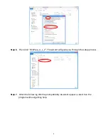
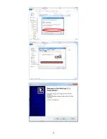
Page 57: ...9 Step 6 Then click WinPcap_4_1_2 The wizard will guide you through the setup process Step 7 When the following WinPcap Compatibility Assistant appears select Run the program without getting help...

Page 58: ...10...

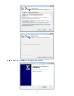
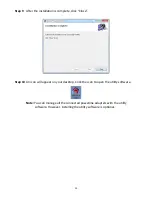
Page 59: ...11 Step 8 After the installation is complete click Finish...

Page 60: ...12 Step 9 Click the Edimax PowerLine Utility the PLC 500Mbps Utility appears click Next to continue Step 10 Select where you want to install the utility software and then click Next...

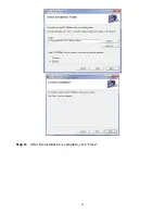
Page 61: ...13 Step 11 After the installation is complete click Close...

Page 62: ...icon will appear on your desktop Click the icon to open the utility software Note You can manage all the connected powerline adapters with the utility software However installing the utility software...

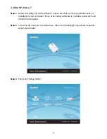
Page 63: ...that no other powerline utility is installed on your computer If any other utility software is installed uninstall it and reboot the computer Step 2 Insert the CD into your CD ROM drive When the foll...

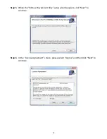
Page 64: ...16 Step 4 If you have not installed WinPcap version 4 1 2 or higher on your computer before The wizard will guide you through the setup process...

Page 65: ...17...

Page 66: ...18 Step 5 When the Edimax PowerLine Utility setup wizard appears click Next to continue Step 6 In the License Agreement screen please select I Agree and then click Next to continue...

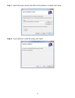
Page 67: ...19 Step 7 Select where you want to install the utility software and then click Next Step 8 If you confirm to install the utility click Next...

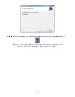
Page 68: ...lete click Close Step 10 An icon will appear on your desktop Click the icon to open the utility software Note You can manage all the connected powerline adapters with the utility software However inst...

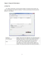
Page 69: ...ys remote powerline adapters in the network Set Name Select a device and click Set Name to rename the device Enter Password By default this column is blank Select a device and click Enter Password to...

Page 70: ...ics tab displays the system information and history of all remote devices The upper panel displays technical data concerning the software and hardware on the host computer and the lower panel displays...

Page 71: ...23 4 3 About Tab The About tab contains some basic information about the software You can also enable or disable the autoscan function under Preferences...

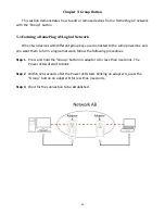
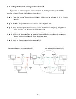
Page 72: ...keys are connected to the same powerline and you want them to form a logical network follow the following procedures Step 1 Press and hold the Group button on adapter A for less than 3 seconds The Pow...

Page 73: ...s the Group button on an adapter in the existing network adapter A or B for less than 3 seconds The Power LED will start to blink Step 2 Within 120 seconds after the Power LED starts blinking on adapt...

Page 74: ...o be removed adapter B for at least 10 seconds Step 2 Wait for adapter B to be disconnected with adapter A C Step 3 Press the Group button on an adapter in another network adapter D for less than 3 se...

Page 75: ...irectly into an electric outlet Using a power strip or surge protector may degrade network performance or completely block network signals This powerline adapter should not be used on GFI protected el...

Page 76: ...posure limits human proximity to the antenna shall not be less than 2 5cm 1 inch during normal operation Federal Communications Commission FCC RF Exposure Requirements SAR compliance has been establis...

Page 77: ...m den Richtlinien 2004 108 EC 2009 125 EC Espa ol El presente equipo cumple los requisitos esenciales de la Directiva 2004 108 EC 2009 125 EC Italiano Questo apparecchio conforme ai requisiti essenzia...

Page 78: ...30...

Reviews: