Hardware Manual
–
CNC310
Page | 15
If y
ou want to use a ‘normal’ relay it’s important to check the current that
a relay needs to switch.
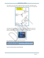
This can be improved by adding a transistor to the output of the board as shown in the image below.
Figure 6. How to switch a power relay.
This image shows how you can control a 5V or 24V (or almost any) relay with the output of the
CNC310. It might be easier to find a board that has all logic already included on one board, and
which can readily be found in the internet. Some will even include optocouplers.
Figure 7. Example of finished relay interface.
We recommended to use standard relays only for low power.
However, our advices remains to use solid state relay.
Please note to always use an anti-parallel diode of 100-200v / 1-2 Amp. Without this
diode the controller may be damaged.


