background image


Owner’s Manual

Bedienungsanleitung

Mode d’emploi

Manuale d’uso

Manual del usuario


202


Copyright © 2003  ROLAND CORPORATION

All rights reserved. No part of this publication may be reproduced in 

any form without the written permission of ROLAND CORPORATION.

201a

Before using this unit, carefully read the sections entitled: 
“USING THE UNIT SAFELY” and “IMPORTANT NOTES” (p. 2; 
p. 4). These sections provide important information 
concerning the proper operation of the unit. Additionally, in 
order to feel assured that you have gained a good grasp of 
every feature provided by your new unit, Owner’s manual 
should be read in its entirety. The manual should be saved 
and kept on hand as a convenient reference.


M-10E


10 CHANNEL 5 STEREO MIXER

Summary of Contents for M-10E

Page 1: ...fore using this unit carefully read the sections entitled USING THE UNIT SAFELY and IMPORTANT NOTES p 2 p 4 These sections provide important information concerning the proper operation of the unit Additionally in order to feel assured that you have gained a good grasp of every feature provided by your new unit Owner s manual should be read in its entirety The manual should be saved and kept on han...

Page 2: ...e If you experience any hearing loss or ringing in the ears you should immediately stop using the unit and consult an audiologist IMPORTANT THE WIRES IN THIS MAINS LEAD ARE COLOURED IN ACCORDANCE WITH THE FOLLOWING CODE BLUE BROWN As the colours of the wires in the mains lead of this apparatus may not correspond with the coloured markings identifying the terminals in your plug proceed as follows T...

Page 3: ...aptor when plugging into or unplugging from this unit or an outlet 103b Any accumulation of dust between the AC adaptor and the power outlet can result in poor insulation and lead to fire Periodically wipe away such dust with a dry cloth Also disconnect the power plug from the power outlet whenever the unit is to remain unused for an extended period of time 104 Try to prevent cords and cables from...

Page 4: ...e temperature and or humidity is very different water droplets condensation may form inside the unit Damage or malfunction may result if you attempt to use the unit in this condition Therefore before using the unit you must allow it to stand for several hours until the condensation has completely evaporated Maintenance 401a For everyday cleaning wipe the unit with a soft dry cloth or one that has ...

Page 5: ...veniently powered using either dry cell batteries on the market 6F22 S 006P 9V or an AC adaptor Microphone Setup Since it is equipped with SENS sensitivity knobs the M 10E can accommodate a broad variety of signals from microphone to line level Overload Indicators The L R OVERLOAD LEDs allow you to set the best signal level for optimum audio performance AUX OUT Jacks Connection to a recording devi...

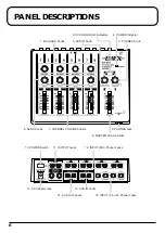
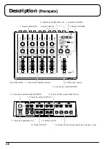
Page 6: ...cks 13 AC Adaptor Jack 16 INPUT 1 4 inch Phone Jacks 14 AUX OUT Jacks 12 INPUT RCA Phono Jacks 10 POWER Switch 11 OUTPUT Jacks 4 POWER Indicator 2 OVERLOAD L R Indicators 3 AUX IN Knob 5 PHONES Knob 9 PHONES Jack 6 SENS Knobs 7 CHANNEL VOLUME Sliders 1 BALANCE Knobs ...

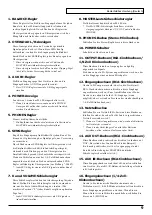
Page 7: ...liders provide volume control for each channel Set these sliders relative to one another to achieve the best audio mix The marked position 0 of each channel indicates the optimum level Each VOLUME slider controls the L R signals in each channel simultaneously 8 MASTER Volume Slider Adjusts the overall output of the M 10E The MASTER slider does not affect the output level of the AUX OUT jacks or th...

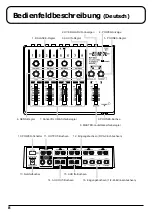
Page 8: ... Netzteilbuchse 16 Eingangsbuchsen 1 4 Zoll Klinkenbuchsen 14 AUX OUT Buchsen 12 Eingangsbuchsen RCA Cinchbuchsen 10 POWER Schalter 11 OUTPUT Buchsen 4 POWER Anzeige 2 OVERLOAD L R Anzeigen 3 AUX IN Regler 5 PHONES Regler 9 PHONES Buchse 6 SENS Regler 7 Kanal VOLUME Schieberegler 1 BALANCE Regler ...

Page 9: ...al Stellen Sie diese Schieberegler relativ zueinander ein um die beste Audio Mischung zu erzielen Die markierte Position 0 jedes Kanals zeigt den optimalen Pegel an Jeder VOLUME Schieberegler steuert die L R Signale in jedem Kanal simultan 8 MASTER Lautstärkeschieberegler Stellt die Gesamtlautstärke des M 10E ein Der MASTER Schieberegler beeinflusst nicht den Ausgangspegel der Buchsen AUX OUT oder...

Page 10: ... entrée Input prises pour casque 1 4 po 14 Prises AUX OUT 12 Prises d entrée prises RCA Phono 10 Interrupteur d alimentation POWER 11 Prises de sortie OUTPUT 4 Indicateur POWER 2 Indicateurs OVERLOAD L R 3 Bouton AUX IN 5 Bouton PHONES 9 Prises pour casque 6 Boutons SENS 7 Curseur VOLUME des canaux 1 Boutons BALANCE ...

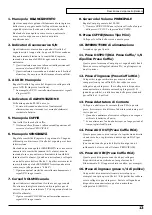
Page 11: ...t de contrêêer le volume de chaque canal Les positionner de manière semblable l un par rapport à l autre pour obtenir le meilleur mélange audio La position marquée 0 pour chaque canal indique le niveau optimal Chaque curseur VOLUME contrôle simultanément les signaux L R g d de chaque canal 8 Curseur de volume MASTER principal Ajuste l ensemble de la sortie du M 10E Le curseur MASTER n affecte pas ...

Page 12: ...6 Prese di ingresso prese 1 4 di pollice 14 Prese AUX OUT 12 Prese d ingresso Prese Cuffie RCA 10 INTERRUTTORE di alimentazione 11 Prese OUTPUT 4 Indicatore di ALIMENTAZIONE 2 Indicatori di sovraccarico S D 3 AUX IN Manopola 5 Manopola CUFFIE 9 Presa CUFFIE 6 Manopole SENSIBILITÀ 7 Cursori VOLUME canale 1 Manopole BILANCIAMENTO ...

Page 13: ...esti indicatori controllano il volume per ogni canale Per ottenere la migliore miscela audio regolare questi cursori La posizione indicata 0 di ogni canale indica il livello ottimale Ogni cursore del VOLUME controlla simultaneamente i segnali S D in ogni canale 8 Cursore del Volume PRINCIPALE Regola l output generale del M 10E Il curosre PRINCIPALE non influisce sul livello di output delle prese A...

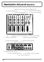
Page 14: ...alida auxiliar AUX OUT 12 Tomas de entrada Tomas tipo RCA 10 Interruptor de alimentación POWER 11 Toma de salida OUTPUT 4 Indicador de alimentación POWER 2 Indicadores izquierdo y derecho L R de sobrecarga OVERLOAD 3 Control de entrada auxiliar AUX IN 5 Control de audífonos PHONES 9 Toma para audífonos PHONES 6 Controles de sensibilidad SENS 7 Deslizadores de volumen de canal VOLUME 1 Controles de...

Page 15: ...e volumen de canal VOLUME Estos deslizadores proporcionan control de volumen para cada canal Ajuste la posición relativa de ambos deslizadores para lograr la mejor mezcla de audio La posición marcada 0 de cada canal indica el nivel óptimo Cada deslizador de volumen VOLUMEN controla las señales izquierda y derecha L R en cada canal simultáneamente 8 Deslizador de volumen maestro MASTER Ajusta la sa...

Page 16: ...alfunction and or damage to speakers or other devices always turn down the volume and turn off the power on all devices before making any connections Connecting Headphones Connect the headphones to the PHONES jack fig 5ae Headphones ...

Page 17: ...f there are batteries 6F22 S 006P 9V in the unit while an AC adaptor is being used normal operation will continue should the line voltage be interrupted power blackout or power cord disconnection 983 Howling could be produced depending on the location of microphones relative to speakers This can be remedied by 1 Changing the orientation of the microphone s 2 Relocating the microphone s at a greate...

Page 18: ...er connect the MASTER OUTPUT L R jacks to the input jacks of the other mixer Desktop media production DTMP is a new way of enjoying music and visual material using your computer A sound module is an electronic sound generating device that you connect to your computer in order to enjoy DTMP IN R L IN R L OUT L IN R L IN R L IN R L OUT R L OUT R BOSS PSA Series Monitor Speakers Sound Module Sound Mo...

Page 19: ...tion Set each Channel VOLUME slider to 0 the marked position and the MASTER Volume slider to the position 943 Always make sure to have the MASTER volume level turned down before switching on power Even with the volume all the way down you may still hear some sound when the power is switched on but this is normal and does not indicate a malfunction fig 6 3 Switch on all the units connected to the M...

Page 20: ... peaks fig 9e 7 Adjust the L R input balance of each channel using the BALANCE knobs 8 Adjust the channel levels relative to one another using the Channel VOLUME sliders 9 Set the overall output volume using the MASTER slider Use a monaural mic and connect the mic to channel 1 MIC or 3 MIC On the channel to which the mic is connected turn the sensitivity knob all the way to the right ...

Page 21: ...ig 3 2 Remove the old battery and replace it with new one fig 4 3 Replace the cover If used improperly batteries may explode or leak and cause damage or injury In the interest of safety please read and observe the following precautions Remove the batteries whenever the unit is to remain unused for an extended period of time If a battery has leaked use a soft piece of cloth or paper towel to wipe a...

Page 22: ...Q The volume level of the instrument connected to INPUT AUX IN MASTER OUTPUT and AUX OUT is too low A Could you be using a connection cable that contains a resistor Use a connection cable that does not contain a resistor ...

Page 23: ...er Volume Slider x 1 Power Switch Indicators Power Indicator Overload Indicator L R Connectors Front Headphone Jack Stereo mini type Rear Input L R x 4 RCA phono type Input L MONO R x 2 1 4 inch phone type Output L R x 1 RCA phono type Output L R x 1 1 4 inch phone type AUX IN L R x 1 RCA phono type AUX OUT L R x 1 RCA phono type AC Adaptor Jack DC 9V Power Supply DC 9V Dry Battery 6F22 S 006P 9V ...

Page 24: ...ndinavia As Filial Finland Elannontie 5 FIN 01510 Vantaa FINLAND TEL 0 9 68 24 020 GERMANY Roland Elektronische Musikinstrumente HmbH Oststrasse 96 22844 Norderstedt GERMANY TEL 040 52 60090 HUNGARY Roland East Europe Ltd Warehouse Area DEPO Pf 83 H 2046 Torokbalint HUNGARY TEL 23 511011 AUSTRIA Roland Austria GES M B H Siemensstrasse 4 P O Box 74 A 6063 RUM AUSTRIA TEL 0512 26 44 260 BELGIUM HOLL...

Reviews: