background image


22


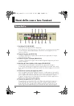
Nomi delle cose e loro funzioni


1. Jack del transformatore CA


Connettere qui il trasformatore CA incluso.


2. Contatto di messa a terra

3. Jack di uscita analogici 1/2 [ANALOG OUTPUT 1/2]


Questi sono jack di uscita analogici per il video e l’audio. Connetterli al monitor del vostro 
televisore, lettore DVD o apparecchio video.


4. Jack d’ingresso analogico [ANALOG INPUT]


Questo è un jack video/audio analogico. Connetterlo al vostro VHS o all’apparecchio video 
di 8mm.


*  Se i cavi del video sono connessi sia al jack d’ingresso del video- S sia al jack d’ingresso composito, 

l’ingresso del video- S avrà priorità sull’altro.


5. Connettore DV 1 [DV1 IN/OUT]


Connetterlo al vostro apparecchio DV o computer.


Non usare contemporaneamente con il connettore DV 2 situato sul pannello frontale del VMC-1 (p. 

20). Se usati contemporaneamente, il vostro apparecchio DV potrebbe non funzionare correttamente.


6. Fessura di Sicurezza (

)


http://www.kensington.com/


Pannello posteriore

6

VMC-1(A5)_e.book 22 ページ 2005年11月14日 月曜日 午後2時51分

Summary of Contents for VMC-1

Page 1: ...port analog video to a notebook computer that has only a DV connector Before using this unit carefully read the sections entitled USING THE UNIT SAFELY and IMPORTANT NOTES p 2 3 p 4 These sections provide important information concerning the proper operation of the unit Additionally in order to feel assured that you have gained a good grasp of every feature provided by your new unit Owner s manual...

Page 2: ... and shock hazards 010 This unit either alone or in combination with an amplifier and headphones or speakers may be capable of producing sound levels that could cause permanent hearing loss Do not operate for a long period of time at a high volume level or at a level that is uncomfortable If you experience any hearing loss or ringing in the ears you should immediately stop using the unit and consu...

Page 3: ...r as listed on the Infor mation page 101b The unit and the AC adaptor should be located so their location or position does not interfere with their proper ventilation 102c Always grasp only the plug on the AC adaptor cord when plugging into or unplugging from an outlet or this unit 103b At regular intervals you should unplug the AC adaptor and clean it by using a dry cloth to wipe all dust and oth...

Page 4: ...cloth or one that has been slightly dampened with water To remove stubborn dirt use a cloth impreg nated with a mild non abrasive detergent After wards be sure to wipe the unit thoroughly with a soft dry cloth 402 Never use benzine thinners alcohol or solvents of any kind to avoid the possibility of discoloration and or deformation Additional Precautions 553 Use a reasonable amount of care when us...

Page 5: ...se e loro funzioni 20 Pannello Pa 20 Pannello posteriore 22 Pannello Inferiore Interruttori DIP 23 Español Nombres de los diferentes elementos y sus funciones 24 Panel frontal 24 Panel posterior 26 Panel inferior Interruptores DIP 27 Setup and Connections 28 Turning the Power On Off 28 Recording Video from a Video Tape to Your DVD Recorder 29 Capturing Video from a Video Tape into Your Computer 30...

Page 6: ...naccuracies in head or tape rotation during analog videotape playback or due to degradation of the analog video signal This function is very useful if you are digitizing the video tape library you have collected over the years You can also apply delay to the audio to correct any timing discrepancies between the video and audio that might be caused by the TBC You can use a front panel button to swi...

Page 7: ...se problems by automatically optimizing the brightness of the analog video You can use a front panel button to switch this function on off p 9 Available only for analog input Correction is not possible if the input video already has over exposed whites or under exposed blacks You cannot convert from NTSC to PAL or vice versa 16 9 screen mode is not supported Each set provides an S video jack and a...

Page 8: ...input to be sent from the analog output 4 Frame synchronizer indicator FRAME SYNC This indicator will light when an analog video signal is input The frame synchronizer corrects synchronization inaccuracies caused by an unstable video signal preventing lost frames and audio dropouts 5 Time base corrector button TBC This corrects the image jitter that often occurs when an analog video deck is playin...

Page 9: ...already has over exposed whites or under exposed blacks 8 Audio level indicator The green indicator will light when an analog audio signal is input The red indicator will light if the input level is excessive Lower the audio input level until the red indicator does not light 9 Power button POWER 10 Brightness knob BRIGHT Turn this knob toward the right to brighten the image or toward the left to d...

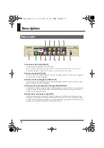
Page 10: ...video audio jack Connect it to your VHS or 8mm video deck If video cables are connected to both the S video input jack and the composite input jack the S video input will take priority 5 DV connector 1 DV1 IN OUT Connect this to your DV device or computer Do not use this simultaneously with the DV connector 2 located on the front panel of the VMC 1 p 8 If you use the two simultaneously your DV dev...

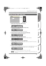
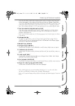
Page 11: ...udio muting time setting switch Depending on the video editing software you re using you may experience audio noise at the beginning of playback if this switch is turned ON In this case use the OFF setting When the VMC 1 is shipped from the factory DIP switch 6 is turned OFF Make sure to turn off the power before you change the settings of the DIP switches on the bottom panel Bottom Panel DIP Swit...

Page 12: ...ie Bildsynchroni sation korrigiert Synchronfehler die durch instabile Videosignale verursacht werden und beugt Bild und Tonverlusten vor 5 Time base corrector Taste TBC Korrigiert das Bildflimmern das oft bei der Wiedergabe von analogen Videogeräten auftritt Normalerweise sollte der Time base corrector eingeschaltet sein Die Video und Audiosi gnale werden dann im Vergleich mit dem Input Signal ver...

Page 13: ... leuchtet wenn ein analoges Audiosignal am Input anliegt Die rote Anzeige leuchtet wenn der Eingangspegel zu hoch ist Reduzieren Sie den Eingangspegel bis die rote Anzeige nicht mehr leuchtet 9 EIN AUS Taste POWER 10 Helligkeitsregler BRIGHT Durch Drehen nach rechts wird das Bild heller durch Drehen nach links wird es dunkler 11 Farbtiefenregler COLOR Durch Drehen nach rechts werden die Farben dun...

Page 14: ...e an Ihren VHS oder 8mm Videorecorder an Wenn Videokabel sowohl an die S Video Eingangsbuchse als auch an die Kombi Eingangsbuchse angeschlossen sind hat der S Video Eingang Priorität 5 DV Anschluss 1 DV2 IN OUT Schließen Sie diesen an Ihr DV Gerät oder an Ihren Computer an Verwenden Sie diesen Anschluss nicht gleichzeitig mit dem DV Anschluss 2 an der Vorderseite des VMC 1 p 12 Wenn Sie beide Ans...

Page 15: ...ormate über DV am Input anliegen 6 Audiostummschaltung Einstellschalter Je nach der verwendeten Video Schnittsoftware können Sie Tonrauschen am Anfang der Wiedergabe feststellen wenn dieser Schalter auf ON gestellt ist In diesem Fall stellen Sie ihn auf OFF Werkseitig ist beim VMC 1 der DIP Schalter 6 auf OFF gestellt Bevor Sie die Einstellungen der DIP Schalter an der Unterseite ändern müssen Sie...

Page 16: ...analo gique à partir de la sortie analogique 4 Indicateur de synchronisation d images FRAME SYNC Cet indicateur s allume lorsqu un signal vidéo analogique arrive en entrée Le synchroniseur d images corrige les imprécisions dues à l instabilité du signal vidéo et empêche la perte d images ou les drop outs audio 5 Bouton de correction du temps TBC Cette fonction corrige l instabilité de l image fréq...

Page 17: ...s ou des barres noires 8 Indicateur de niveau audio Le témoin vert s allume lorsqu un signal audio analogique arrive en entrée Le témoin rouge s allume si le niveau d entrée est excessif Réduire le niveau d entrée audio jusqu à extinction du témoin rouge 9 Bouton de mise sous tension POWER 10 Bouton de luminosité BRIGHT Tourner ce bouton vers la droite pour éclaircir l image ou vers la gauche pour...

Page 18: ... analogique Se branche sur votre magnétoscope VHS ou 8 mm L entrée S vidéo est prioritaire lorsque des câbles vidéo sont connectés sur la prise jack d entrée S vidéo et la prise jack d entrée composite 5 Connecteur DV 1 DV1 IN OUT Se branche sur appareil DV ou ordinateur Ne pas utiliser en même temps que le connecteur DV 2 situé sur la face avant du VMC 1 p 16 En cas d utilisation simultanée l app...

Page 19: ...a DV 6 Commutateur de réglage silencieux Selon le logiciel d édition vidéo utilisé un bruit audio peut se faire entendre au début de la lecture si ce commutateur est en position MARCHE ON Dans un tel cas le mettre en position ARRÊT OFF Lorsque le VMC 1 est expédié de la fabrique le commutateur DIP 6 est en position ARRÊT OFF Mettre l appareil hors tension avant de modifier le réglage des commutate...

Page 20: ...sioni della sincronizzazione causate da un segnale video instabile evitando in questo modo la perdita d immagine e la caduta del suono 5 Pulsante del correttore del tempo base TBC Serve a correggere l instabilità dell immagine che spesso si verifica quando un apparecchio video analogico sta riproducendo Di norma occorre tenere accesa questa funzione Se viene accesa i segnali video e audio verranno...

Page 21: ...llo d immissione dell audio fino a quando non si spegne l indicatore rosso 9 Pulsante corrente POWER 10 Manopola luminosità BRIGHT Girare questa manopola verso destra per schiarire l immagine oppure verso sinistra per scurire l immagine 11 Manopola aumento del colore COLOR Girare questa manopola verso destra per aumentare il colore oppure verso sinistra per diminuire il colore 12 Manopola per la s...

Page 22: ...logico Connetterlo al vostro VHS o all apparecchio video di 8mm Se i cavi del video sono connessi sia al jack d ingresso del video S sia al jack d ingresso composito l ingresso del video S avrà priorità sull altro 5 Connettore DV 1 DV1 IN OUT Connetterlo al vostro apparecchio DV o computer Non usare contemporaneamente con il connettore DV 2 situato sul pannello frontale del VMC 1 p 20 Se usati con...

Page 23: ...Hz 12 bit formato audio canale 4 via DV 6 Interruttore del tempo di silenziamento A seconda del progamma di montaggio video che si utilizza è possibile rilevare disturbi audio all inizio della riproduzione se questo interruttore è impostato su ON In questo caso impostare l interruttore su OFF Quando VMC 1 esce dalla fabbrica l interruttore DIP 6 è impostato su OFF Assicurarsi di spegnere prima di ...

Page 24: ...ica 4 Indicador del sincronizador de fotogramas FRAME SYNC Este indicador se encenderá cuando se esté recibiendo una señal de vídeo analógica El sincronizador de fotogramas corrige las imprecisiones de la sincronización producidas por una señal de vídeo inestable lo que evita la pérdida de fotogramas y de audio 5 Botón corrector de base de tiempo TBC Corrige la inestabilidad de la imagen que se pr...

Page 25: ...as 8 Indicador del nivel de audio El indicador verde se encenderá cuando se esté recibiendo una señal de audio analógica El indicador rojo se encenderá si el nivel de entrada es excesivo Se deberá reducir el nivel de entrada de audio hasta que no se encienda el indicador rojo 9 Botón de encendido POWER 10 Botón de brillo BRIGHT Al girar este botón hacia la derecha se ilumina la imagen y hacia la i...

Page 26: ... de un jack de vídeo y audio analógico Conéctelo al VHS o a la pletina de vídeo de 8 mm Si los cables de vídeo se conectan al jack de entrada de S vídeo y al jack de entrada compuesta la entrada de S vídeo tendrá prioridad 5 Conector DV 1 DV1 IN OUT Conecte este conector al dispositivo DV o al PC No utilice este conector simultáneamente con el conector de DV 2 situado en el panel frontal del VMC 1...

Page 27: ... de 4 canales 32 kHz y 12 bits a través de DV 6 Interruptor de ajuste de tiempo de silenciador de audio En función del software de edición de video que use podría experimentar ruido de audio al principio de la reproducción si este interruptor está encendido ON En ese caso use la opción apagado OFF Cuando se envía el equipo VMC 1 desde la fábrica el interruptor 6 DIP está apagado OFF Asegúrese de d...

Page 28: ...xternal ground When the unit is grounded a slight hum may occur depending on the particulars of your installation If you are unsure of the connection method contact the nearest Roland Service Center or an authorized Roland distributor as listed on the Information page Unsuitable places for connection Water pipes may result in shock or electrocution Gas pipes may result in fire or explosion Telepho...

Page 29: ...ward the right and set it so it s a little before the position at which the red indicator lights If the red indicator lights the sound is distorting 6 Adjust the brightness BRIGHT color depth COLOR color hue CUE and contrast CONTRAST knobs until you are satisfied with the image You can switch the time base corrector button TBC 3D Y C separator button 3D Y C and automatic brightness adjustment butt...

Page 30: ...re the position at which the red indicator lights If the red indicator lights the sound is distorting 6 Adjust the brightness BRIGHT color depth COLOR color hue CUE and contrast CONTRAST knobs until you are satisfied with the image You can switch the time base corrector button TBC 3D Y C separator button 3D Y C and automatic brightness adjustment button AGC on off as necessary The 3D Y C separator...

Page 31: ...n the VMC 1 is used with this four channel audio format When converting from analog to DV only the two main channels will be recorded regardless of how DIP switch 5 p 11 on the bottom panel is set Nothing will be recorded on the two sub channels When converting from DV to analog only the two main channels will be output while the unit remains at the factory settings If you turn on DIP switch 5 p 1...

Page 32: ...ed to the VMC 1 s AC adaptor jack and is plugged into an AC outlet Make sure that the video cable and audio cable are correctly connected to the input jack and output jack If copy protected video is input to the VMC 1 an image with decreased brightness and contrast will be output The audio input level is too high Turn the audio input level knob so that the red indicator does not light The audio mi...

Page 33: ... input successfully Turning off the 3D Y C separator may help For some images turning on the automatic brightness compensation AGC button may produce virtually no improvement In such cases you can adjust the brightness knob and contrast knob Correction is not possible if the input image already contains over exposed whites and under exposed blacks If you input video from a game device or similar u...

Page 34: ...dBu DIN AUDIO 1 kHz Nominal Output Level IHF A type Audio Channel Separation 70 dBu DIN AUDIO 1 kHz Nominal Output Level IHF A type Input Output Connectors Front DV connector i LINK 4 pin connector comforms to IEEE1394 Rear DV connector i LINK 4 pin connector comforms to IEEE1394 S Video input 4 pin mini DIN type Y 1 0 Vp p C 0 286 Vp p 75 ohms Video input RCA phono type 1 0 Vp p 75 ohms Audio inp...

Page 35: ...ghtness 9 29 30 32 brillo 25 C canale 4 23 COLOR 9 13 17 21 25 29 30 color bar 32 color depth 9 29 30 color hue 9 29 30 composite 29 33 computer 30 31 Conector DV 24 26 Connecteur DV 16 18 Connettore DV 20 22 Contatto di messa a terra 22 contrast 9 29 30 32 contraste 17 25 contrasto 21 copy protected 32 correcteur de temps 16 corrector de base de tiempo 24 correttore del tempo base 20 D DIP switch...

Page 36: ...inosità 21 S sampling rate 11 19 Samplingrate 15 saturation de couleur 17 security slot 10 sfumatura del colore 21 Sicherheitsschlitz 14 sincronizador de fotogramas 24 sincronizzatore dell immagine 20 sotto 23 sub 11 15 19 27 31 32 S video 29 33 synchroniseur d images 16 T tasso di campionatura 23 TBC 6 8 12 16 20 24 29 30 teinte des couleurs 17 television 31 Terminal de toma de tierra 26 time bas...

Page 37: ...VMC 1 A5 _e book 37 ページ 2005年11月14日 月曜日 午後2時51分 ...

Page 38: ...VMC 1 A5 _e book 38 ページ 2005年11月14日 月曜日 午後2時51分 ...
Page 39: ...limits are designed to provide reasonable protection against harmful interference in a residential installation This equipment generates uses and can radiate radio frequency energy and if not installed and used in accordance with the instructions may cause harmful interference to radio communications However there is no guarantee that interference will not occur in a particular installation If thi...

Page 40: ...511011 CZECH REP K AUDIO Kardasovska 626 CZ 198 00 Praha 9 CZECH REP TEL 2 666 10529 Roland Systems Group U S 14830 Desman Road La Mirada CA 90638 U S A TEL 714 521 8000 AUSTRIA GERMANY ITALY IRELAND UNITED KINGDOM EDIROL Europe Ltd Studio 3 4 114 Power Road London W4 5PY U K TEL 0 20 8747 5949 BELGIUM FRANCE LUXEMBOURG SWITZERLAND HOLLAND SPAIN PORTUGAL Roland Iberia S L Paseo Garca Faria 33 35 0...

Reviews: