CMU 100 - RS485 to 2x RS232 fallback switch
3.3 APPEARANCE
3.4 HARDWARE DESCRIPTION
This configuration of device is made from main board (power supply, LEDs, switches and logic
witch), one RS485, and two RS232 interface boards.
3.4.1 MAIN BOARD
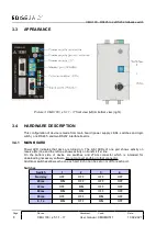
Power LED indicates that device is turned on. The right LEDs of one port shows activity on
receive (Rx) line and the left one shows activity on transmit (Tx) line.
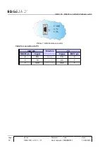
On the bottom side of device are switches and JTAG connector which is intended for
downloading necessary software. Do not connect anything to that connector.
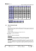
Additional switches allows echo on each port. Echo can be set on or off for each port.
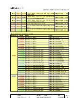
Switches
Switch
1
2
3
4
No delay
OFF
OFF
OFF
OFF
20 ms
ON
OFF
OFF
OFF
40 ms
OFF
ON
OFF
OFF
60 ms
ON
ON
OFF
OFF
80 ms
OFF
OFF
ON
OFF
0,1 s
ON
OFF
ON
OFF
Page:
Device:
Document:
Code:
Date:
8
User manual CMUMU511
Picture 3: CMU 100 / x.5.1.1 - 17 front view (left) & bottom view (right)


