background image

 2 


Parts List


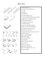
1.  Connector Sleeve (1x) 

2.  Two-part channel and plastic chain (1x) 

3.  C-rail (2x) 

4.  Carriage (1x) 

5.  Door bracket (1x) 

6.  Control housing with cord (1x) 

7.  Tensioner, tensioning bolt M8 x 80mm, and spring (1x) 

8.  Angle bracket for rail mid-attachment (4x) 

9.  Thick washer 1-1/4” dia (4x) 

10.  U-fitting long stud with collar (1x) 

11.  U-fitting short bolt (1x) 

12.  Long pin and clips 

OR lock nut/bolt 

(2x) 

13.  Medium pin and clip 

OR lock nut/bolt 

(1x) 

14.  Short pin and clip 

OR lock nut/bolt 

(2x) 

15.  Lag bolt 5/16” x 1-1/2” (10x) 

16.  Carriage bolt M8 x 25mm, lock washer and nut (4x) 

17.  Release cord grip (1x) 

18.  Electric end (1x) *

NOT USED

19.  Non-electric end (1x) 

20.  Electric end with cord (1x) 

21.  Photoeye set (1x) 

22.  Rail mid-attachment bracket (2x) 

23.  Wall button (1x) 

24.  Remote transmitter (2x) 

25.  Boomerang curved brace (1x) 

26.  Limit stop set (marked “H” and “V”) (1x) 

27.  Rail end bracket (2x) 

10 

11 

12 

13 

14 

15 

16 

18 

21 

22 

23 

25 

26 

19 

24 

27 

17 

20 

Summary of Contents for Autoslide

Page 1: ...Installation Manual For Sliding Garage Doors Edison Autoslide...

Page 2: ...d clips OR lock nut bolt 2x 13 Medium pin and clip OR lock nut bolt 1x 14 Short pin and clip OR lock nut bolt 2x 15 Lag bolt 5 16 x 1 1 2 10x 16 Carriage bolt M8 x 25mm lock washer and nut 4x 17 Relea...

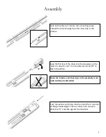
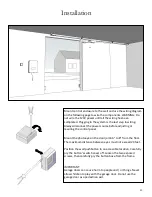
Page 3: ...p to the carriage cord by sliding it on and knotting the cord Hang the chain out as shown and thread it onto the sprocket on the underside of the carriage Note the position of the chain with guide as...

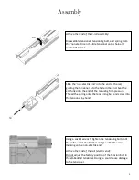
Page 4: ...chain into the tensioner on the electric end with cord Turn the electric end by 90 to lock into position Push the electric end firmly into the end of the C rail until its flange meets edge of the rai...

Page 5: ...the end Seat the end fully onto the end of the rail using firm pressure Thread the spring onto the tensioning bolt and screw into the tensioner by hand Using a socket wrench tighten the tensioning bo...

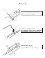
Page 6: ...lick and the carriage will freeze its position Insert two M8 x 25mm carriage bolts into rail mid attachment bracket as shown Slide onto one end of the rail leaving at about the 1 3 position Repeat for...

Page 7: ...ge as shown With thick washer and medium length pin and clip Position end bracket on assembly as shown at left Thread long pin into end then fix into place with two clips Repeat for other end of rail...

Page 8: ...with short length pin and clip The section of the brace with 3 holes should be running parallel to the track Attach the other U fitting to the other end of the brace with another short pin and clip F...

Page 9: ...th 5 16 lag screws Note Attachment must be to adequate framing or strapping Drywall attachment only is not permitted The track must not come into contact with the door s supporting sliding track at an...

Page 10: ...nd U fitting assembly to determine best placement Mark the location of the brace s two mounting holes Cut door bracket to length if desired Plug end with plastic end cap provided and install on door w...

Page 11: ...justing or rewiring the control panel Mount the photoeyes in the door jamb 6 to 8 from the floor The maximum distance between eyes must not exceed 20 feet Position the wall pushbutton in an accessible...

Page 12: ...e boot Reconnect the terminals IMPORTANT Always have the power disconnected when adjusting any wiring on the system Wire the accessories and safety photoeyes to the terminals numbers as shown Polarity...

Reviews: