SGC
Pin
Mode RS232
Mode RS422/
RS485
1
Rx
Rx+
2
CTS
Rx-
3
Tx
Tx-
4
RTS
Tx+
5
GND
GND
6
DSR
7
DCD
8
DTR
9
RI
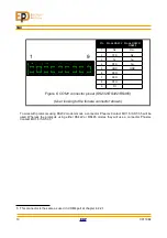
Figure 6: COM1 connector pinout (RS232/RS422/RS485)
(User looking to the female connector shown)
To work with protocols using RS232 modem mode a connector Phoenix Contact MC 1,5/9-ST-3,5 will be
used. Whereas the protocols using either RS422 or RS485 modes they will use a connector Phoenix
Contact MC 1,5/5-ST-3,5
5 This connector is the same as used in COM4 port at chapter 4.2.2.1
13
00110E4
1
9
Summary of Contents for SGC Series
Page 31: ...6 FUNCTIONS 00110E4 EDP 26 Illustration 8 VPD unit logic diagram ...
Page 53: ...10 SCHEMATICS 10 SCHEMATICS 00110E4 EDP 48 ...
Page 54: ...SGC 49 EDP 00110E4 ...
Page 55: ...10 SCHEMATICS 00110E4 EDP 50 Illustration 13 Connection diagram ...
Page 56: ...SGC Illustration 14 SGC195 Connection diagram 51 EDP 00110E4 ...
Page 58: ...SGC 11 SIZE 53 EDP 00110E4 Drawing 1 Front and side views of SGC180 and SGC195 devices ...
Page 59: ...11 SIZE Drawing 2 Top and bottom view of SGC180 device 00110E4 EDP 54 ...
Page 60: ...SGC Drawing 3 Top and bottom view of SGC195 device 55 EDP 00110E4 ...


