6 FUNCTIONS
6.1.3 SETTINGS
NAME
RANGE
STEP OTHER
Phase pickup threshold
0.5 – 8 A
0.25 A
Phase timing type
EI-VI-NI-DT-DI
Phase curve number
0.1 – 10
0.1
Phase timing
0.5 – 10 s
0.1 s
Phase instantaneous threshold
1 – 25 times
0.1 t
Phase additional instantaneous time
0.1 – 10 s
0.1 s
Phase overcurrent block threshold
DI/ 1-25 times
1 t
Table 25: Protection function 50/51 settings
NAME
RANGE
STEP OTHER
Neutral pickup threshold
0.125 – 4 A
0.125 A
Neutral timing type
EI-VI-NI-DT-DI
Neutral curve number
0.1 – 10
0.1
Neutral timing
0.5 – 10 s
0.1 s
Neutral instantaneous threshold
1 – 25 times
0.1 t
Neutral additional instantaneous time
0.1 – 10 s
0.1 s
Table 26: Protection function 50N/51N settings
6.1.4 OPERATION
PICKUP
When the line current reaches the pickup level, the protection function starts the timing.
The return from pickup threshold is 95% of the nominal pickup threshold.
OVERCURRENT BLOCKING
To ease the protection coordination with other elements (i.e: fuses), a programmable block threshold can
be configured which disables the overcurrent trip when the line current is greater than the setting.
50/50N FUNCTION
The 50/50N function trips instantaneously when the line current surpasses the threshold. This setting is
relative to the pickup current.
Optionally, the 50/50N function can also be timed.
15 All settings refer to secondary values.
00110E4
36
Summary of Contents for SGC Series
Page 31: ...6 FUNCTIONS 00110E4 EDP 26 Illustration 8 VPD unit logic diagram ...
Page 53: ...10 SCHEMATICS 10 SCHEMATICS 00110E4 EDP 48 ...
Page 54: ...SGC 49 EDP 00110E4 ...
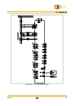
Page 55: ...10 SCHEMATICS 00110E4 EDP 50 Illustration 13 Connection diagram ...
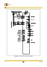
Page 56: ...SGC Illustration 14 SGC195 Connection diagram 51 EDP 00110E4 ...
Page 58: ...SGC 11 SIZE 53 EDP 00110E4 Drawing 1 Front and side views of SGC180 and SGC195 devices ...
Page 59: ...11 SIZE Drawing 2 Top and bottom view of SGC180 device 00110E4 EDP 54 ...
Page 60: ...SGC Drawing 3 Top and bottom view of SGC195 device 55 EDP 00110E4 ...


