SGC
6.2.4 OPERATION
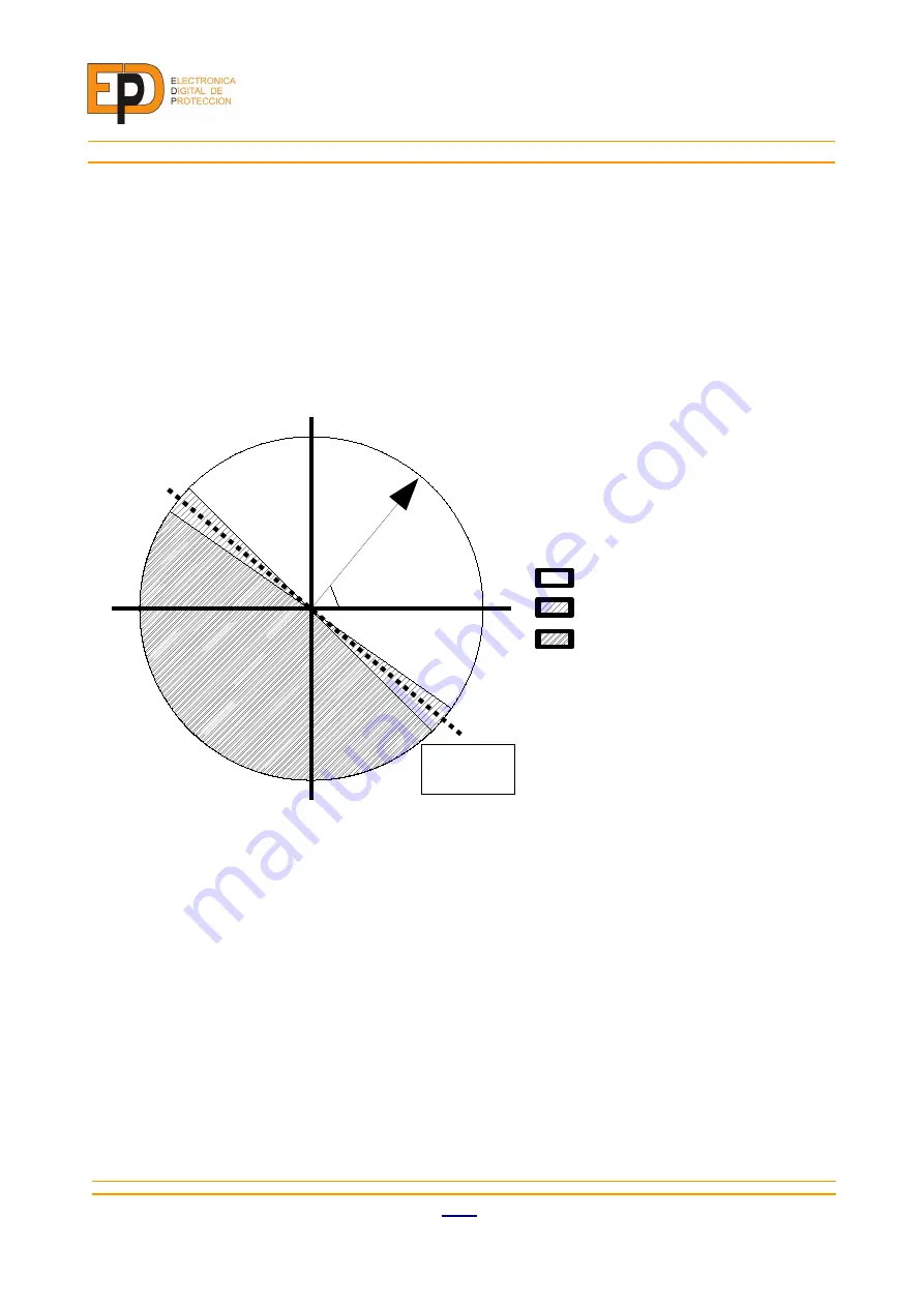
The unit's operation zones are defined by the maximum torque angle (MTA) and the configured direction
(in or out).
A minimum polarizing voltage can be set to disable the unit when the line voltage is too low.
The “allowing/blocking” signal is routed to other protection units (overcurrent protection, FPD, …). When
they have the “directional” flag enabled they can be blocked by this unit.
The following Illustration shows a phasor diagram of the operation zones.
39
00110E4
Illustration 12: Operation zones diagram
0º
90º
270º
MTA
Input
Output
ɸi -ɸv
Allowing zone
Blocking zone
Transition zone
±5º
Summary of Contents for SGC Series
Page 31: ...6 FUNCTIONS 00110E4 EDP 26 Illustration 8 VPD unit logic diagram ...
Page 53: ...10 SCHEMATICS 10 SCHEMATICS 00110E4 EDP 48 ...
Page 54: ...SGC 49 EDP 00110E4 ...
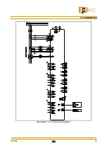
Page 55: ...10 SCHEMATICS 00110E4 EDP 50 Illustration 13 Connection diagram ...
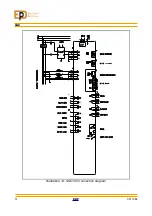
Page 56: ...SGC Illustration 14 SGC195 Connection diagram 51 EDP 00110E4 ...
Page 58: ...SGC 11 SIZE 53 EDP 00110E4 Drawing 1 Front and side views of SGC180 and SGC195 devices ...
Page 59: ...11 SIZE Drawing 2 Top and bottom view of SGC180 device 00110E4 EDP 54 ...
Page 60: ...SGC Drawing 3 Top and bottom view of SGC195 device 55 EDP 00110E4 ...


