6 FUNCTIONS
6.3 MEASUREMENT FUNCTION
6.3.1 DESCRIPTION
The SGC performs a wide range of line parameter measurements which can be obtained local or
remotely.
Sign of RMS values indicates direction of current flow.
6.3.2 SETTINGS
NAME
RANGE
STEP
OTHER
Phase Current Transformer Ratio
10-1000 / 1
1
Neutral Current Transformer Ratio
10-1000 / 1
1
Phase Voltage Transformer Ratio
10-1000 / 1
1
Neutral Voltage Transformer Ratio
10-1000 / 1
1
Voltage Transformer Connection
Phase-phase/
Phase-neutral
Phase Nominal Current
1 – 5000 A
1 A
For relative readings
Phase Nominal Voltage
1-100 kV
1 kV
For relative readings
Neutral Nominal Current
1 – 5000 A
1 A
For relative readings
Neutral Nominal Voltage
1-100 kV
1 kV
For relative readings
Calculate neutral current
On/Off
Calculate neutral voltage
On/Off
Table 30: Measurement function settings
The voltage transformer connection establish if the input voltage are line-ground or line-line voltage. In
each case the other value is internally calculated by the controller.
The nominal power is also calculated internally as a product of nominal voltage by nominal current.
The device can also calculate the neutral voltage/current by the other phase voltages in the case that is
not able to connect directly.
6.3.3 SIGNALS
All the direct and indirect measured analog values available form the SGC are listed in the table on the
next page,
00110E4
40
Summary of Contents for SGC Series
Page 31: ...6 FUNCTIONS 00110E4 EDP 26 Illustration 8 VPD unit logic diagram ...
Page 53: ...10 SCHEMATICS 10 SCHEMATICS 00110E4 EDP 48 ...
Page 54: ...SGC 49 EDP 00110E4 ...
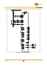
Page 55: ...10 SCHEMATICS 00110E4 EDP 50 Illustration 13 Connection diagram ...
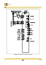
Page 56: ...SGC Illustration 14 SGC195 Connection diagram 51 EDP 00110E4 ...
Page 58: ...SGC 11 SIZE 53 EDP 00110E4 Drawing 1 Front and side views of SGC180 and SGC195 devices ...
Page 59: ...11 SIZE Drawing 2 Top and bottom view of SGC180 device 00110E4 EDP 54 ...
Page 60: ...SGC Drawing 3 Top and bottom view of SGC195 device 55 EDP 00110E4 ...


