18
MAINTENANCE
GENERAL
CHECKLIST
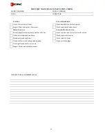
The following should be incorporated in a planned maintenance schedule to ensure that the equipment is well maintained. In all
cases the various sections of the equipment should be examined and any defects logged for replacement/repair. For
performance analysis a detailed service/maintenance log book should be kept outlining problems encountered and defects
found during routine maintenance. Examples can be found at the end of this section
.
GENERAL COMMON COMPONENTS
CABINET AND FRAME - EXAMINE
1) Examine the cabinet exterior for any obvious defects or damage and repair as necessary.
2) Remove the front, side and rear panels and examine the cabinet interior for signs of damage or corrosion. Repair any
damage found and restore the surface finish where corrosion has occurred.
3) Refit the front, side and rear panels and restore the electrical supply to the unit.
4) Record and report any defects found during the inspection.
DRIVE PACKAGE
1) Remove the unit front panels and inspect the fan motor for any loose electrical connections and retighten as necessary.
2) Inspect the fan impellers and remove any debris.
3) Check that the fan impellers are securely mounted on the fan shaft. Rotate the impellers and ensure freedom of movement.
4) Inspect the bearings for signs of wear. If any excessive movement is noticed the bearings must be renewed.
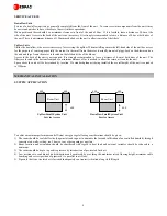
5) Check the drive belts monthly for signs of wear and proper tension. Pressing on the belts midway between the sheave and
pulley should produce approx. 12.5mm of movement. Belts that are too tight can cause excessive bearing wear.
DRIVE BELT RE-TENSIONING
1) Correctly tension the belts by adjusting the fan motor slide base as necessary.
2) After adjusting or renewing the belts, always check that the motor mounts are tight. Loose mounts will produce vibration
that may damage the unit.
Note: If belts appear cracked or worn, they should be renewed with matched belts (identically sized). On units with twin belt
drives both belts should be renewed at the same time. With proper care, belts should provide a long service life.
AIRFLOW SWITCH
1) Open the unit front panel and inspect the airflow switch located below the electric panel for any loose electrical connections
and retighten as necessary.
2) Examine the pressure sensing tube between the switch and the fan casing for defects, damage and loose connections.
Renew the tube if necessary.
3) Refit the unit front panel and restore the electrical supply to the unit.
4) Record and report any defects found during the inspection.
SAFETY NOTE
This equipment is designed for safe operation provided it is installed, maintained and serviced in
accordance with the guidelines laid down in this section of the manual. They should therefore be studied
in advance by any person wishing to work on the equipment
The equipment contains electrical components at high voltage. The main power isolation switch should
therefore be opened before access is gained to the equipment
Care should be taken to avoid hands and clothing becoming entangled in the rotating parts.
Care should be taken when working near the steam outlet pipe. This can remain hot for some time after
the unit is shut down.
Any service and maintenance operations requiring access to the inside of the equipment while in
operation should be carried out by an appropriately qualified or experienced person who is fully aware of
the potential dangers and precautions to be taken.

