background image

3

GENERAL

On receiving the equipment it should be checked to ensure that it is complete and in perfect condition. The carrier should be notified
immediately, in writing, of any damage that might have been caused in transit.

HANDLING

Always keep the unit vertically upright and do not leave it out in the open.  The unit can be moved with a pallet truck. If a forklift is
being used ensure the forks extend beyond the pallet. Care should be taken not to damage the bottom of the unit. If a crane is being
used  to  move  the  unit  leave  the  packaging  intact  and  place  spreader  bars  across  the  top  of  the  unit  to  prevent  the  slings  causing
damage.    The  unit  should  be  moved  as  near  as  possible  to  the  installation  position  before  removing  the  cardboard  packing  and  the
pallet.

UNPACKING THE UNIT

1) Cut the three straps binding the unit taking care to avoid any backlash caused by their tightness.
2) Remove the lid.
3) The cardboard sleeve will then unravel itself revealing a plastic dust cover.
4) Remove dust cover. If it is a downflow model, to remove the front panels use the key attached to the sensor on the top of the unit.
5) Remove the two bolts securing the unit to the skid (19 mm spanner).
6) Manoeuvre the unit carefully from the pallet. If it is necessary, use rollers underneath the unit to locate it in its final position.
7) If the unit requires a plenum fix same before final positioning.
8) Ensure the unit is positioned on a level floor.

POSITIONING

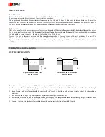
Single Circuit Units.
The  Modular Range is built on a level base and its positioning is most important. The unit should be firmly supported on the floor
itself or on an optional floorstand.
Ensure  that  the  unit  is  level  in  all  directions  as  failure  to  do  so  will result  in  operational  problems,  particularly  with  regards  to
drainage.  Care  should  be  taken  in  manoeuvring  the  unit  as  the  paintwork  could  be  damaged.  Use  rollers  where  possible  and  apply
pressure to the bottom of the unit for final positioning. Before final positioning ensure that inaccessible panels are correctly fitted and
plenums are secured.

ATTACHING THE PLENUM

The plenum and unit are pre-drilled. At the time of installation remove the grilles from the plenum and secure the plenum internally by
means of self tapping screws provided. Also secure to the back of the unit.

AIR COOLED CONDENSERS

Locate these as close to their final position as possible before uncrating. A full set of assembly instructions are attached to the unit.
Headers and return bends are not to be used in the moving of the condenser.
When locating the condenser ensure that it is in an open area with unrestricted airflow shaded from direct sunlight.
Install in an environment free of debris to avoid the fins becoming blocked.
Ensure that some form of vibration elimination is installed between the condenser legs and the roof of the building.
Condensers are not to be ducted on either side.
Where noise is critical in relation to the condenser make ensure that this is clearly specified at the time of order.

INSTALLATION

Summary of Contents for Model 12 220V/3PH/60Hz

Page 1: ...Close Control Small System Range Chilled Water Units Installation Operation Maintenance Manual 50 60Hz ...

Page 2: ...D Details 14 Alarms 15 MAINTENANCE General 18 Common Components 18 Electric Panel Inspection Functional Tests 19 Steam Humidifier Canister Cleaning Removal 20 Fault Finding Guide 21 Monthly Maintenance Inspection Check 23 Annual Maintenance Inspection Check 24 While every precaution has been taken to ensure accuracy and completeness in this manual EDPAC assumes no responsibility and disclaims all ...

Page 3: ... positioned on a level floor POSITIONING Single Circuit Units The Modular Range is built on a level base and its positioning is most important The unit should be firmly supported on the floor itself or on an optional floorstand Ensure that the unit is level in all directions as failure to do so will result in operational problems particularly with regards to drainage Care should be taken in manoeu...

Page 4: ... of the unit The filters are located in the bottom front panel a minimum distance of 1m is needed to allow the return air to enter the unit Space above the unit will be determined by location If a standard plenum is being installed the overall height of the unit is extended to 2380mm MECHANICAL INSTALLATION SYSTEM APPLICATION To achieve maximum performance and efficient energy usage following cons...

Page 5: ...aracteristics should comply with the following values In the case of high water pressure a pressure reducing valve calibrated to between 3 4 bar should be fitted Inlet water temperature must not exceed 50o C It is recommended to install a shut off valve and a mechanical filter with the wire mesh size less than 50µm The humidifier pan drain connection is a 22 mm female connection The humidifier dra...

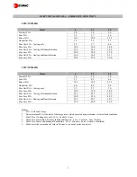
Page 6: ...pe Size mm 12 12 12 Condenser Conns Inlet Outlet 30 C mm 22 16 22 16 28 22 Condenser Conns Inlet Outlet 35 C mm 22 16 28 22 28 22 Condenser Conns Inlet Outlet 40 C mm 22 16 28 22 35 28 Condenser Conns Inlet Outlet 45 C mm 22 16 35 28 35 28 Condenser Conns Inlet Outlet 50 C mm 28 22 35 28 35 28 Scroll Compressor 50Hz ZR34K ZR61K ZR81K Scroll Compressor 60Hz ZR28K ZR48K ZR72K Compressor Quantity No ...

Page 7: ...Max Unit FLA Cooling only 3 7 5 9 7 6 Max Fuse FLA 10 0 15 0 20 0 Max Unit FLA Cooling Dehumidification 23 5 25 7 32 9 Max Fuse FLA 30 0 35 0 45 0 Max Unit FLA Heating and Humidification 27 5 29 7 38 7 Max Fuse FLA 35 0 40 0 50 0 Notes 1 FLA Full Load Amps 2 Unit maximum FLA is the total of the components which operate during maximum electrical load conditions 3 Max FLA of Cooling only unit FLA Co...

Page 8: ...Max Unit FLA Cooling only 2 3 3 3 4 1 Max Fuse FLA 10 0 10 0 10 0 Max Unit FLA Cooling Dehumidification 14 9 15 9 20 2 Max Fuse FLA 20 0 20 0 25 0 Max Unit FLA Heating and Humidification 16 8 19 2 23 0 Max Fuse FLA 20 0 25 0 30 0 Notes 1 FLA Full Load Amps 2 Unit maximum FLA is the total of the components which operate during maximum electrical load conditions 3 Max FLA of Cooling only unit FLA Co...

Page 9: ...ontroller The controller compares this information to the set point and proportional band values programmed into its memory it then commands the air conditioner to treat the air as appropriate CUSTOMER CONNECTIONS Power cables to the load break switch should be sized in compliance with local codes see electrical data for permissible fuse size Power cables required are 3 phase and a neutral 2 5mm m...

Page 10: ...Max voltage fan air volume is at set point plus control band min voltage fan air volume at set point Max voltage air volume is typically design air volume and min air volume is typically around 60 for chilled water units Minimum value needs to insure that there are no hot spots due to lack of airflow and that there is no loss of sensible cooling capacity to latent cooling capacity at the cooling c...

Page 11: ...urn air temperature setpoint The solenoid valve or modulating valve will energise b As the return air temperature rises above the return air setpoint the controller will cancel the heating process by de energising the solenoid valve or modulating valve Note Heating can occur when compressor 1 is operating in the dehumidification mode and the return air temperature is below the return air temperatu...

Page 12: ...verflow tube The drain valve opens periodically to drain water and reduce salt concentration in the boiler It is also used to drain the humidifier completely under alarm conditions SYSTEM OPERATION The humidifier interface PCB maintains the electric current dissipated in the boiler at the programmed set point The PCB therefore changes the immersion level of the electrodes by adding or draining wat...

Page 13: ...8 times the rated current generally due to the fill valve overload The valve remains open for more than 10 minutes without the threshold of current set point 10 being reached and without the level electrodes intervening e g due to failure in the water supply blocked intake filter defective fill valve power probe current transformer contactor blown fuses encrusted electrodes etc ...

Page 14: ...e alarm condition has occurred If there are multiple alarms then using the arrow up down buttons lets you scroll through them Up arrow button Displays the program windows and allows the user to set the value of the control parameter Down arrow button Displays the program windows and allows the user to set the value of the control parameter In default menu pressing down arrow button displays unit o...

Page 15: ...gh Entering Water Temperature AL 16 Low Entering Water Temperature AL 17 Compressor 1 Run Hours AL 18 Compressor 2 Run Hours AL 19 Fan Run Hours AL 20 Return Air Temperature Probe Fault Or Offline AL 21 Entering Water Temperature Probe Fault Or Offline AL 22 External Air Temperature Probe Fault Or Offline AL 23 Supply Air Temperature Probe Fault Or Offline AL 24 Return Air Humidity Probe Fault Or ...

Page 16: ...M error alarm AL 51 Alarms EVO n1 EEV probe S1 fault AL 52 Alarms EVO n1 EEV probe S2 fault AL 53 Alarms EVO n1 EEV probe S3 fault AL 54 Alarms EVO n1 EEV probe S4 fault AL 55 Alarms EVO n1 EEV driver offline AL 56 Alarms EVO n1 EEV driver battery discharged AL 57 Alarms EVO n2 EEV Motor Error AL 58 Alarms EVO n2 MOP high temperature of evaporation AL 59 Alarms EVO n2 LOP low temperature of evapor...

Page 17: ...an n4 AL 84 Warning Ziehl Abegg fan n4 AL 85 Alarm Ziehl Abegg fan n4 Offline AL 86 Alarm Ebmpapst fan n1 AL 87 Warning Ebmpapst fan n1 AL 88 Alarm Ebmpapst fan n1 Offline AL 89 Alarm Ebmpapst fan n2 AL 90 Warning Ebmpapst fan n2 AL 91 Alarm Ebmpapst fan n2 Offline AL 92 Alarm Ebmpapst fan n3 AL 93 Warning Ebmpapst fan n3 AL 94 Alarm Ebmpapst fan n3 Offline AL 95 Alarm Ebmpapst fan n4 AL 96 Warnin...

Page 18: ...NING 1 Correctly tension the belts by adjusting the fan motor slide base as necessary 2 After adjusting or renewing the belts always check that the motor mounts are tight Loose mounts will produce vibration that may damage the unit Note If belts appear cracked or worn they should be renewed with matched belts identically sized On units with twin belt drives both belts should be renewed at the same...

Page 19: ...HILLED WATER VALVES 1 Remove the unit front panels 2 Visually inspect the valve s for damage and ensure that the connections are not leaking 3 Ensure that the valve s are securely mounted in position 4 Ensure that the actuator s are securely fitted to the valve body 5 Refit the unit front panels and restore the electrical supply to the unit 6 Record and report any defects found during the inspecti...

Page 20: ...ICIENT PASSAGE OF ELECTRICAL CURRENT 1 Drain the water completely See Controls Manual for details on drain procedure 2 Disconnect the power supply to the equipment 3 Unscrew the steam pipe from the boiler 4 Disconnect the wiring to the main electrodes and the level electrodes 5 Unhook the holding spring and unscrew the humidifier bottle by rotating it anti clockwise on its axis 6 Remove the bottle...

Page 21: ...rature setpoint Refer to User Control Manual 2 The heater does not work properly if fitted 1 Check the heating elements 2 Check the electric heater MCB 3 In the case if electric heater alarm eliminate the cause and re set the safety thermostat 5 The control system does not operate properly See User Control Manual Check that the display and processor and or the sensor function properly 6 Thermal lo...

Page 22: ...trical resistance of the motor windings After re set measure the supply voltage and current drawn 5 The pressure drop in the air distribution system ducts ceilings flooring plenum grilles etc is too high 1 Check the design and sizing of the air distribution system THE HEATER SAFETY THERMOSTAT CUTS OUT 1 Lack of airflow See LACK OF AIR FLOW Heater trip alarm 2 thermostat faulty connection wire Chec...

Page 23: ...ion of steam hoses DRIVE PACKAGE CHILLED WATER SECTION Blower impellers moving freely and free of debris Check that the valve motor is correctly secured Check belt tension and condition Check pipework is secure Bearings in good condition Check joints for leaks Check airflow switch setting and operation Check coil for damage Check pulley and sheave are secure Inspect blower anti vibration mounts GE...

Page 24: ...and condition Check electrical connections Bearings in good condition Check operational sequence Check airflow switch setting and operation Check pulley and sheave are secure Inspect blower anti vibration mounts STEAM HUMIDIFIER Check humidifier bottle for deposits Check condition of steam hoses Inspect inlet filter Check fill drain valves CHILLED WATER SECTION Check that the valve motor is correc...

Reviews: