E D R O
D
y n a
W
a s h
®
T
h r e e
P
o c k e T
W
a s h e r
- e
x T r a c T o r s
64
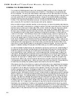
The contents of RAM program memory are retained by battery back-up as the contents of the
memory may be lost in the event of power loss to the PLC. The battery is not used while the
PLC is energized. The life cycle of the battery is dependent on how often the power to the PLC
is disconnected. The battery should last a minimum of three years without power to the PLC and
up to ten years if the PLC is continually energized. If power is lost and the battery is dead the
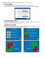
program is lost and must be reloaded. This can be easily accomplished by use of PLC transfer
module. If it is determined the battery backup is not dead and the PLC fault remains, the prob-
lem is inside the PLC and the PLC input/output unit must be replaced.
When a electronic logic-controlled machine or process stops, it is almost invariably a field device,
such as a limit switch, solenoid valve, or tripped overload, that has caused the action. These field
devices can be on the input or output side of the control. Electronic relays for input and outputs
have proven themselves to be very reliable and have a wide range of complex applications.
However, logic controllers and their associated circuitry, do sometimes fail. If a failure does occur,
it is important to be able to first make a decision as to whether the problem is in the electronic
control or in the field. The first thing to check when troubleshooting a electronic logic-based con-
trol is to confirm the control power on is off. If the control power light is off, there is likely an open
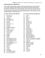
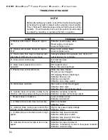
circuit in the supply power or control circuitry (see troubleshooting guide). A status bar on the
touch screen indicates current machine functions during program operation. If the control is not
responding, caught in a loop or not indicative of the machine’s action (status bar say Extract and
machine is stuck in wash speed for over 90 seconds), press the System function button, then
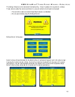
press Run to re-boot the HMi software, and navigate to reload a program. An error screen will
appear to disallow loading of the program and then allow you to end the existing program.
In order to facilitate troubleshooting, the maintenance personnel must have an understanding of
the operation of the machine corresponding to the programmed formulas (i.e. knowing what the
machine is supposed to be doing at a certain point in the formula and why). If an output such
as a solenoid valve, motor contactor, etc. is not activated and the corresponding Y output indi-
cator light is off (indicating the output terminal is not energized) you must search backwards to
determine what conditions are preventing the output from coming on. In most cases, the search
will lead to an input (level or setting) that is not in the correct state to satisfy the programming
requirements. Refer to the control schematic identifying the specific input and output terminals
corresponding to each field device. When an X input, such as the level switch, is preventing the
formula from proceeding, the specific physical input must be checked for continuity.
If the inputs are in the correct state (i.e. water level is attained), and an output does not energize
as shown by the control’s indicator light, check the corresponding voltage at the output terminal
on expander unit. If voltage is not present, the expander unit relay may be loose or faulty and
must be re-seated or replaced. If voltage is present on the Y output, the problem is an open
circuit in the field wiring or a faulty field device such as an external relay, a stuck solenoid, or a
tripped overload. Although the control’s X and Y indicator lights corresponding to each individual
input or output are a convenient troubleshooting tool, they do not guarantee that an internal out-
put relay has closed. The indicator lights are controlled independently of the corresponding out-
put relay - the light only indicates the program has sent the signal to close the relay. The actual
voltage must be measured at the terminal in question in order to verify the state of the terminal.
If voltage is present, there is either a break in the circuit going to the solenoid or the valve itself
is stuck closed. If a Y output relay is damaged, it may be the result of an electrical short in the
field device it is connected to. Therefore, it is imperative to troubleshoot and correct any electri-
cal problem with the field device prior to replacing the expander unit or PLC control otherwise the
new control will also fail. In the majority of troubleshooting cases, the underlying cause of the
problem will be in the field devices or an open circuit in the field input/output wiring to the control.
GENERAL PLC TROUBLESHOOTING


