

E D R O
D
y n a
W
a s h
®
T
h r e e
P
o c k e T
W
a s h e r
- e
x T r a c T o r s
87
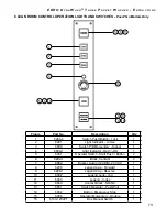
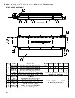
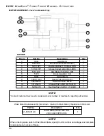
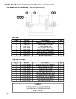
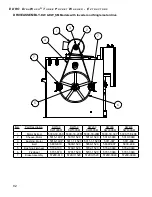
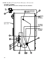
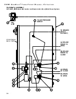
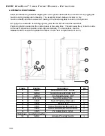
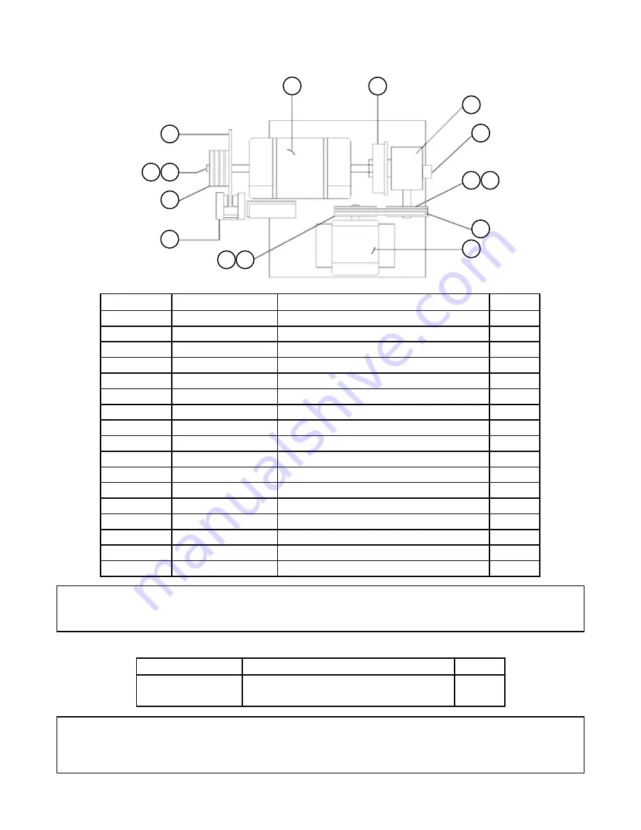
MOTOR ASSEMBLY-
PassThru
Models Only
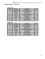
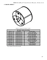
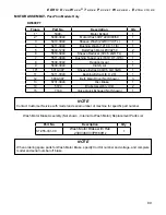
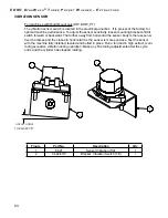
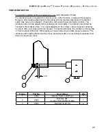
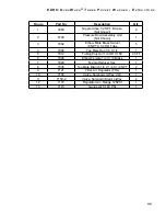
Wash Motor Brake Assembly (Not shown - Internal to Wash Motor) Replacement Parts List
NOTE
When ordering spare parts for Wash Motor Brake, specify Coil Kit number and voltage, and complete
model and serial number off brake.
Part No.
Description
Qty
S1-055-331-00
Wash Motor Brake with Hub
230V/460V/3PH/60Hz
1
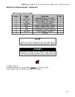
NOTE
*Contact Customer Service with model and serial number of machine for specific part number.
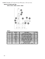
Figure
Part No.
Description
Qty
1*
5300-
Motor Extract
1
2*
5400-1520
Motor Wash - 2 HP
1
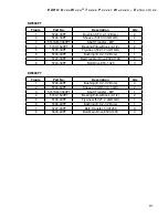
3
5410-1520
Sheave Wash (3V3.35 TL 1 GR)
1
4
5411-1520
Bushing Wash (1610 X 7/8 TL)
1
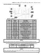
5
5840-1234
Belt Wash Motor #3VX250
2
6
5510-1520
Sheave Reducer (3V5.0 TL 1GR)
1
7
5411-1520
Bushing Wash (1610 X 7/8 TL)
1
8
5500-1520
Reducer Gear
1
9
5600-1520
Clutch, Air
1
10
5310-1520PT
Sheave Extract (4A5.6/B6.0 TL)
1
10
5310-50-1520PT
Sheave Extract (4A7.0/B7.4 TL)
1
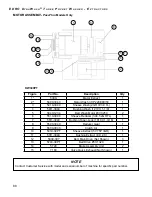
11
5311-1520
Bushing Extract(SK X 2.0 QD)
1
12
5830-1520PT
Belt Main Drive (Not Shown)
4
12
5830-50-1520PT
Belt Main Drive #B-116
1
13
5731-1520
Disc Brake - B/P
1
14
5729
Brake Assembly Unit
1
15
7160
Valve Quick Exhaust
1
14
12
13
11
10
3
4
9
1
8
15
6
7
5
2
DW150PT - DW200PT


