background image

EDS - INFORMAZIONI TECNICHE

10

fig. 2

P

U

T

E

S

R

O

S

N

E

S

V

U

-

Y

R

O

M

E

M

-

Y

A

L

E

D

E

M

I

T

-

0

5

L

F

T

E

S

2

S

H

C

T

I

W

S

P

I

D

R

O

S

N

E

S

V

U

Y

T

I

V

I

T

I

S

N

E

S

R

I

+

V

U

Y

A

L

E

D

E

M

I

T

)

d

n

o

c

e

s

(

Y

R

O

M

E

M

1

2

S

U

T

A

T

S

3

4

S

U

T

A

T

S

5

6

S

U

T

A

T

S

N

O

N

O

M

U

M

I

X

A

M

N

O

N

O

0

3

N

O

F

F

O

N

O

N

O

F

F

O

M

U

I

D

E

M

O

T

M

U

M

I

X

A

M

N

O

F

F

O

0

2

F

F

O

F

F

O

F

F

O

F

F

O

N

O

M

U

I

D

E

M

O

T

M

U

M

I

N

I

M

F

F

O

N

O

0

1

F

F

O

F

F

O

M

U

M

I

N

I

M

F

F

O

F

F

O

5

fig. 3

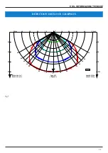
Fig. 4

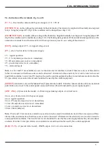
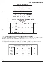
Fig. 2 shows how the Dip Swtitch S3 must be set to adjust the sensitivity of the IR sensors
Fig. 3 indicates how the Dip Swtitch S2 must be set to adjust the sensitivity of the UV sensor, the alarm time delay of the
IR + UV section (the delay is the same for both) and the alarm memory (activated or not activated) )

Note 

- Intervention time delays are related to both the UV and IR sections simultaneously.

In addition, the times indicated above may vary by an increase of 5-30% depending on the programmed sensitivity.

P

U

T

E

S

R

O

S

N

E

S

-

R

I

-

0

5

L

F

T

E

S

3

S

H

C

T

I

W

S

P

I

D

Y

T

I

V

I

T

I

S

N

E

S

1

R

I

2

R

I

3

R

I

1

2

3

4

5

6

S

U

T

A

T

S

N

O

N

O

N

O

N

O

N

O

N

O

M

U

M

I

X

A

M

F

F

O

N

O

F

F

O

N

O

F

F

O

N

O

M

U

M

I

X

A

M

O

T

M

U

I

D

E

M

N

O

F

F

O

N

O

F

F

O

N

O

F

F

O

M

U

M

I

N

I

M

O

T

M

U

I

D

E

M

F

F

O

F

F

O

F

F

O

F

F

O

F

F

O

F

F

O

M

U

M

I

N

I

M

1

S

-

W

O

D

N

I

W

L

A

C

I

T

P

O

G

N

I

T

A

E

H

P

U

T

E

S

H

C

T

I

W

S

P

I

D

1

S

8

-

1

7

-

2

6

-

3

5

-

4

c

c

V

2

1

)

V

5

1

-

2

1

(

N

O

F

F

O

N

O

N

O

c

c

V

4

2

)

V

0

3

-

4

2

(

F

F

O

N

O

F

F

O

N

O

Summary of Contents for FL - 50

Page 1: ...or UV IR Explosion Proof Execution FL 50 TECNICAL INSTALLATION MANUAL SAFETY INSTRUCTIONS EDS V Ca Nova Zampieri 6 37057 S G Lupatoto VERONA Tel 045 547529 Fax 045 8750065 Email eds eds eu Web www eds eu Date 20 11 2019 File FL50_ist_11_2019 ...

Page 2: ...ectionagainstelectromagneticinterference 6 Introducea shieldedcableaccordingtolocalstandardwithsectionappropriatetothedistance 1 5mm2 up to 500m 7 After making the conductors make the connections as shown in fig 6 8 Make the adjustments for the sensitivity delay of intervention setting of the relays fig 2 3 90 10 and chap 10 and setting of the optics heating system power supply if existing Otherwi...

Page 3: ...ithEN60079 17 verificationandmaintenanceofelectricalsystems locatedinroomswhereexplosiveatmospheresmayformandwhichspecifiesthequalificationofthepersonnelassignedto thesechecksandmaintenance 4 2 The FL 50 detector can be installed in areas with danger of explosion Zone 1 Zone 2 Zone 21 Zone 22 ItmustnotbeinstalledinahazardousareaclassifiedasZone0 4 3 Thetechnicaldataindicatedonthecontainermustberes...

Page 4: ...Thismakesthedetectorhighlyimmunetofalsealarms 7 PRECAUTIONS BEFORE INSTALLATION 7 1 Allinstallationandmaintenanceoperationsmustbecarriedoutwhenthedeviceisnotlive 7 2 Whenthecoverisopened greatcaremustbetakennottodamagetheO ringtypegasket 7 3 Toavoiddamagingthecover bottomcoupling carefullycleanthesurfacesbeforecouplingthem 8 IMPORTANT INSTALLATION RULES 8 1 Preventthedetectorfrombeingexposedtodire...

Page 5: ...g two detectors pointed towards each other 9 3 Theinstallationheightisinrelationtotheareatobecontrolled bearinginmindthattheviewingangleofthedetector is100 Candthatitsmaximumflamedetectiondistance withatargetgeneratedbyaflamereferencefrompetrolwith a height of 20 cm within a 33x33x5 cm tray is 50 m The graph in fig 4 indicates the protected area as a function of distance and sensitivity The sensit...

Page 6: ...sitivity level can be lowered to avoid possible false alarms Levels 2 and 3Vmust not be used by control equipment as they do not indicate an alarm Also the 4 V pre alarm is not an alarm level and should not be used by the control equipment MTEST terminaltocarryouttheManualTest ifpresentinthemodel Itmustbeconnectedwithacabletoanexternal push button on or near to the control panel connected between ...

Page 7: ...the correct NC NA position of the relays 10 2 Sensitivity adjustment The FL 50 detector has two independent adjustment possibilities for the IR and UV section IR 4 sensitivity levels using the Dip_Switch S3 high medium high medium low low fig 9 and tab fig 2 UV 4 sensitivity levels using the Dip_Switch S2 high medium high medium low low fig 10 and tab fig 3 10 3 Delay of intervention FL 50has4dela...

Page 8: ...ime delay on the detector the red LED lights up to indicate the alarm condition YellowLED steadylight indicatestheFaultconditionduringmanualorautomaticTest 11 3 If possible perform a function test as described in point 12 1 12 MANUAL AND AUTOMATIC TEST if present in the model TheFL 50detectorcanbeequippedasanoptionwitha ManualandAutomaticTestsystemforcheckingtheoperation oftheIRandUVsensorsandclea...

Page 9: ...of explosion In these environments the flame detectors can not be tested with the use of flames or similar devices FLT 20isexplosion proofEx dIICT6ATEXcertifiedandthereforecanbeusedinpotentiallyexplosiveenvironmentsclassified as Zone 1 2 20 21 22 It should be remembered that in environments with danger of explosion it is absolutely not necessary to carry out a functional test by lighting a flame 1...

Page 10: ...ensitivity of the UVsensor the alarm time delay of the IR UV section the delay is the same for both and the alarm memory activated or not activated Note Intervention time delays are related to both the UVand IR sections simultaneously In addition the times indicated above may vary by an increase of 5 30 depending on the programmed sensitivity P U T E S R O S N E S R I 0 5 L F T E S 3 S H C T I W S...

Page 11: ...I TECNICHE 11 fig 5 DETECTION DISTANCE GRAPHICS 25 50 75 100 sensibilità 50 m 40 30 20 10 distance m sensitivity degree DS1987A 25 33 40 50 0 10 20 35 45 60 50 60 50 45 35 20 10 40 40 distanza m gradi 10 20 30 40 50 m ...

Page 12: ...FAULT RELAY T P NAA NCF T 3 12 24 Vdc external button for manual Test V R load 50 300 ohm EARTH TERMINAL NCA ANALOG OUT 4 20mA ALARM RELAY JP2 JP1 VERONA ITALY EDS srl NOTE theindicationsoftherelays is relate totheinitial setting of therelaysinthe normally unexcited configuration for the Alarmrelay and notenergized for theFaultrelay JP1jumpersinposition2 3andJP2in position2 3seechapter 10 1andfig ...

Page 13: ...EDS INFORMAZIONI TECNICHE 13 fig 7 FL50 VIEW OF THE TERMINAL BOARD FL50 TERMINAL BOARD VIEW 4 20mA module RS 485 module analog terminal board and Mtest power and relays terminal board ...

Page 14: ...indows opticalwindows FL50 VISTE ESTERNE FL 50 EXTERNAL VIEW elementi di protezione delle ottiche vite di terra groundscrew finestre ottiche coperchioconguarnizioneOR cover with O Ring insulating gasket ghiera di fissaggio GH ringnutGH supportoorientabile adjustablesupport ...

Page 15: ...EDS INFORMAZIONI TECNICHE 15 FL 50 INTERNAL VIEW VISTA INTERNA fig 10 dipswitchS2 S2 S1 fig 9 dip switch S3 jumper JP1 JP2 JP2 JP1 S3 1 2 3 1 2 3 ...

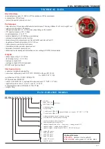
Page 16: ...ting principle is based on the detection of infrared radiation IR and ultraviolet light emitted by a flame UV Thedetector dependingonversion canbeequippedwiththe followingsensors 3 IR infrared sensors with different spectral windows 1 UV ultraviolet sensor Theuseofthismulti sensortechnologyandamicroprocessor controlledcircuitryandsoftwarewithspecificalgorithms make thedetectorveryefficientandatthe...

Page 17: ...rt optional Mechanical data container inlightaluminumalloy execution explosion proof CE 0722 II 2GD Ex db op is IIC T6 Gb Ex tb IIIC T85 C Db certification ATEX CESI11ATEX019X IP65protection EN60529 cable exit hole M20x1 5 optional threads on request 1 2 NPT 1 2 GK application areas zone 1 zone 2 zone 21 zone 22 containerdimensionswithbracket 130x185mm weight 3 Kg TECHNICAL DATA FL50 X X X X X X X...

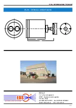
Page 18: ...ICHE 18 EDS srl V Cà Nova Zampieri 6 37057 San Giovanni Lupatoto Verona Italy tel 0039 045 547529 fax 0039 045 8750065 email eds eds eu web www eds eu 68 0 80 0 126 0 187 5 130 0 FLANGIA FLANGE Ø5 0 FL 50 OVERALL DIMENSIONS ...

Reviews: