EDS - INFORMAZIONI TECNICHE
12
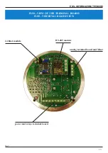
Fig. 6
WIRING DIAGRAM
FA
ULT RE
LA
Y
1
R-
V-
AMP -
SH
IE
LD
CO
M
F
CONNECT TO V-
1
AL
A
R
M
RE
LA
Y
2
ANALOG OUT 0-5V
R+
RS485 OUT
CO
M
A
AMP +
NA
F
MTEST
2
POWE
R SUPPLY
P
3
DS1814H
RS485 modul
FAULT RELAY
T-
P
NA
A
NC
F
T+
3
12
/2
4 V
dc
external button for manual Test
V+
R load 50-300 ohm
EARTH TERMINAL
NC
A
ANALOG OUT 4-20mA
ALARM RELAY
JP2
JP1
VE
R
O
N
A
(I
TA
LY
)
ED
S srl
NOTE -
the indications of the relays is relate to the initial setting of the relays in the normally unexcited configuration
for the Alarm relay and not energized for the Fault relay (JP1 jumpers in position 2-3 and JP2 in position 2-3 see chapter
10.1 and fig.9 ).


