EDS - INFORMAZIONI TECNICHE
2
FL-50 QUICK INSTALLATION
The FL-50 detector is supplied with the following initial setting:
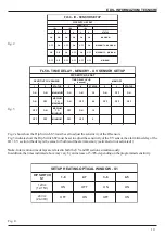
- IR sensitivity: maximum
- UV sensitivity: maximum
- UV + IR time delay: 5 seconds
- Optics heating (if present): set for nominal 24 Vdc power supply
- Alarm relay: normally de-energized (JP1 jumper in position 2-3)
- Fault relay: normally de-energized (JP2 jumper in position 2-3)
If you already have an FL-50 detector installation experience, follow the steps below.
If you don't have this experience read the whole manual.
1 - Remove the detector from the packaging
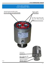
2 - Release the bracket from the detector by unscrewing the GH ring (fig.8)
3 - After choosing the correct position to obtain the best protection of the area, fix the bracket to the wall or
ceiling using 4 expansion caps. Connect a 4 mm2 minimum cable to the earth screw (fig.8)
4 - Disassemble the cover of the detector by unscrewing the 4 hexagonal head screws and slowly remove
the electronic optical assembly
5 - Install an ATEX certified cable gland on the corresponding inlet on the base of the appliance.
Respect the 1/2 "NPT - 1/2" GK - M20x1.5 threads. We recommend to use the cable gland EDS type PSC-
12-EMI for maximum protection against electromagnetic interference
6 - Introduce a shielded cable according to local standard with section appropriate to the distance (1.5mm2
up to 500m)
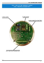
7 - After making the conductors, make the connections as shown in fig.6.
8 - Make the adjustments for the sensitivity, delay of intervention, setting of the relays (fig.2-3-90-10 and
chap.10) and setting of the optics heating system power supply (if existing).
Otherwise, use the initial factory settings
9 - Reinstall the cover with the electronic optical assembly in the base and tighten the 4 hexagonal head
screws. Tightening torque 3 Nm.
10 - Install the appliance on the bracket and, using the GH ring (fig.8), orient the appliance so that its viewing
angle covers the area to be protected
11 - Connect the appliance cable to the control panel
12 - Give power to the appliance and perform a Test run as indicated in chap. 12
NOTE
These instructions are for all FL-50 UV + IR models.
FL-50 IR can be supplied with 1 UV 1-2-3 IR sensors.
Depending on the model, you will have to use the adjustments according to the installed sensor.
The models and sensors installed are the following:
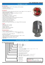
- FL50-1-1-X-X-X-X-X-X ......... sensor installed UV + IR1
- FL50-1-2-X-X-X-X-X-X ......... sensor installed UV + IR1 + IR2
- FL50-1-3-X-X-X-X-X-X ......... sensor installed UV + IR1 + IR2 + IR3
For example, if you use the FL50-1-1-X-X-X-X-X-X model, you must make the adjustments indicated in these
instructions on the IR1 sensor.


