EDS - INFORMAZIONI TECNICHE
8
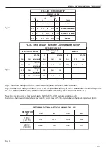
FL-50 is supplied with the heating system set for the 24Vdc power supply. If the detector is powered at 12Vdc, the
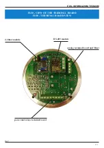
heating system must be set for 12Vdc using the Dip-Switch S1 (fig.10).
The table in fig.4 indicates the settings for the 12 and 24Vdc voltages.
The automatic heating system intervenes if the room temperature drops below 5 ° C. Above 5 ° C the system is deactivated.
11
-
VERIFICATION OF OPERATION
After installation, after the configuration operations and after completely closing the box, it is possible to power the detector
and proceed to check the operation.
11.1
- If false alarms are generated, it must be checked whether disturbing elements exist in the area controlled by the
detector. If necessary, change the sensitivity and time delay settings to compensate for these anomalies.
11.2 - LED indications
When the detector switches on, the White, Red and Yellow LEDs flash three times.
White LED
- flashing every 10 seconds - indicates normal operation
- steady light - when both the IR and UV sections are both activated due to the presence of a flame, a pre-alarm indication
is immediately generated by permanent switching on of the white LED (walk test / preallarm).
Red LED
- steady light - when the detector detects the IR + UV radiation of the flame for a time longer than the programmed time
delay on the detector, the red LED lights up to indicate the alarm condition
Yellow LED
- steady light - indicates the Fault condition during manual or automatic Test
11.3
- If possible, perform a function test as described in point 12.1.
12
-
MANUAL AND AUTOMATIC TEST
(if present in the model)
The FL-50 detector can be equipped as an option with a Manual and Automatic Test system for checking the operation
of the IR and UV sensors and cleaning the optical windows. The Test consists in activating 1 IR source and 1 UV source
inside the FL-50 . Activation is activated periodically automatically by the internal electronics or by pressing on a remote
button installed outside the potentially explosive area or inside the explosive zone provided it is in explosion-proof execution
with characteristics suitable for installation in this area , connected as indicated in the instruction manual.
12.1 - Manual Test
Warning!
- This test, if successful, causes a true Alarm signal (Alarm output relay is energized and the analogue output
goes to 5V (or 20mA ).
Before performing this Test it is necessary to consider the consequences derived from the detector alarm.
Therefore it is advisable to block the peripherals (sirens, extinguishing systems, etc.) connected to the detector alarm relay
to avoid damage. To allow manual testing, the MTEST terminal must be connected to an external Normally Open NO push-
button (NA). The push-button poles must be connected to the MTEST terminal and the other pole to the detector power
supply negative. To execute the Manual Test, press the button for about 1 second. The detector performs a series of checks


