EDS - TECHNICAL INSTRUCTIONS
10
11 - FAULT OUTPUT
11.1
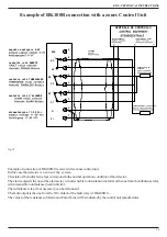
- On the terminal block of the detector is available the contact of fault/anomaly relay. This relay is normally excited and will turn not-
excited if the followings conditions are verified:
• the signal goes down under the 90% setting value (optical beam completely interrupted by an obstacle)
• the circuit of autocompensation has reached the limit (when this happens to proceed it is necessary to the maintenance of the detector)
• operation failure (it means breakdown of some component)
Attention
: As stated by the relevant standards, the fault output can be used for remote signaling, but must not be used for inhibiting the
alarm signal.
11.2
-
Total Obscuration Option
It is possible to activate a function for rapid total obscuration (<1 sec, 90%) that activates only the fault output (30 second delay) and not
the alarm.
This could be useful to indicate that an obstacle was accidentally introduced through the path of the optical beam.
This operational mode is only working when total obscuration is rapid (<1 sec).
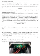
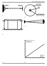
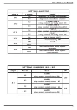
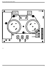
To activate this function operator must insert the JP8 jumper (fig. 9).
Test of this function can be done with a piece of non reflecting material quickly covering the reflector. After around 30 seconds of reflector
covering, the fault output should be activated.
12 - ALARM MEMORY
12.1
- The RK100R(S) is endowed with alarm memory that can be switched ON/OFF through the jumper JP5 (fig.9):
• jumper JP5 in position 1-2 - memory not activated (OFF)
• jumper JP5 in position 2-3 - activated (ON)
When the memory is activated, if the detector goes to alarm, the alarm relay and the frontal red Led remain activated until it doesn't stop
the alarm and is not removed power for over 5 seconds. When the memory is not activated, if the detector goes to alarm, the alarm relay
and the frontal Led are disarmed as soon as it stops the alarm.
12.2
- Memory of the data of configuration and setting.
In case of black out the memory inside preserve the data. To the return of the feeding the detector, later once of initialization of about 2
minutes, returns to normal operation
13 - DETECTOR’S ACTIVATION
13.1
- Put the jumper of initial Set JP1 in position 1-2 (OFF)
13.2
- The blue Led of Alignment flashes in particular way (2 flash slow flashes - 1 break - 2 fast flashes, repeated)
13.3
- Install the cover. The operation of detector’s closing must be done within 5 minutes. The level of the signal will be decreased
because of the absorption caused by the cover
13.4
- The inside electronics attends 5 minutes for the installation of the cover and later performs a rapids procedure (time 1-2 minutes) take
again the signal of the RK100-R to 4,7-5V
13.5
- After this phase of adjustment, the detector becomes operational. The blue Led of Alignment stops (detail cap.10.2) and and it
begins to flash as described in 10.6
13.6
- every 10 seconds the blue Led will emit a short flash that points out the normal operations of the detector. In case of alarm the frontal
red LED turned fixed ON and remains turned ON until it stops the state of alarm or, if it is setted the function of memory, until the supply
is not removed for 5 seconds (v. cap.14)
14 - VERIFICATION OF OPERATION
14.1
- Verification of the sensitive circuit to obscuration..
The verification is carrried out simply by darkening
the reflector
with an opaque screen. After 10 seconds, detector alarm relay must
activate / not activate (cap.5.2 - jumper JP7) and the alarm frontal red Led must be turned ON. After, remove the screen, the relay of alarm


