EDS - TECHNICAL INSTRUCTIONS
9
If this signal adjustment is critical or, if turning the trimmer with small movements, you notice big changes on the signal level, review
as described in cap. 8.10.
8.14
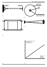
- It must be checked out that, since the detector founds its operation on the reflection of the projected beam, this reflection is effected by
the FX reflector only and not from other elements.
To be certain that the signal is produced by the reflection of its FX reflector and not from other elements, it is useful to do a simple verification.
It is necessary to obscure the reflector with a non reflecting screen (opaque).
In that case the signal on SIG terminal must decrease under 0,5V. (check indications in the following pages).
8.15
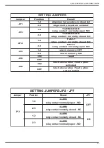
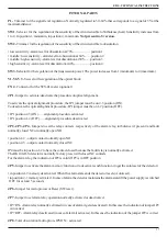
- Select the alarm threshold level of the circuit sensible to obscuration acting on the selector SW2 keeping in mind the following :
• position 1 - low sensitivity - obscuration alarm threshold set to 70% .........................signal level 1.5V
• position 2 - low to medium sensitivity - obscuration alarm threshold set to 60% .....signal level 2.0V
• position 3 - medium to high sensitivity - obscuration alarm threshold set to 50%.....signal level 2.5V
• position 4 - high sensitivity - obscuration alarm threshold set to 40%...........................signal level 3.0V
8.16
- Sensitivity must be regulated according to the environmental situation. The setting must normally be a medium sensitivity level, but
in case of dusty and perturbed environments it will be useful to set a lower sensitivity level.
9 - SETTING OF THE TURBULENCE CIRCUIT
(not relevant for -S version)
9.1 -
The RK100-R detector is equipped with a special additional circuit for the detection of air Turbulence (heat). This circuit is
independent from the classic obscuration one and in particular situations it can be used to increase the performance of the detector. If
these particular situations are not present the Turbulence circuit can be left unused.
9.2
- This circuit is particularly useful when, for environmental reasons, the optical beam smoke detector must be installed at distances from the
ceiling higher than the nominal. When the fire begins, it produces smoke clouds and hot air bubbles that go up. When these bubbles intercept
the infrared beam, they perturbate it because they produce a change of the optical-physical characteristics of infrared beam. These changes are
obviusly correlated in time. This circuit has been designed to detect these changes and, when these changes reach the programmed amplitude
and time lenght, an alarm signal is generated.
The advantage of this circuit is the quicker fire detection, because the fire is detected in its beginning phase. A typical example is the complete
protection of the dome of a church with important pictures on its surface. The linear optical beam smoke detectors must be installed at the
baseline of the dome and therefore much lower than the ceiling. In this case using the turbulence (heat) detection circuit is very useful to
improve the detection.
9.3
- Selection of the sensitivity level of the circuit sensitive to Turbulence(heat).
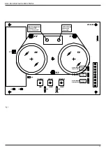
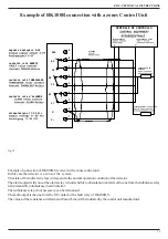
The operation is performed acting on selector SW1 of the detector that has 4 positions (fig.9).
• sensitivity increases from 1 to 4
• position 1 : minimum sensitivity
• position 4 : maximum sensitivity
The regulation must be performed with caution, because with an higher sensitivity a quicker response time is obtained, but also the
probability of false alarm is increased. So the sensitivity selection must be done according to the environmental conditions. If these
conditions are good, an high sensitivity regulation is possible. If in the environment, because of the normal working conditions, dust's
clouds, vapor or smoke are systematically produced, it will be necessary to adjust the sensitivity to a lower level, so that these factors
doesn't generate false alarms.
10 - AUTOCOMPENSATION
10.1
- The inside electronics of the detector is endowed with a special circuit of auto-compensation of the signal. If the detector is installed
inside a particularly dusty place, the dust that is deposited on the front surface of the cover causes a drop of the signal. This drawback
is automatically eliminated by the circuit of autocompensation.


