3
EDS - TECHNICAL INFORMATION
4 - OPTICAL ALIGNMENT
4.1
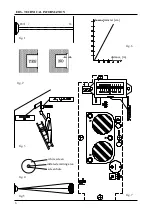
- Go on with the optical alignment between the
device and the FX reflector. To make this operation
easier, it is suggested to do it in a reduced
environment light, and to proceed in the following
way:
a) Shift the JP2 jump to position 2-3 and rotate
the P4 internal trimmer for the sensitivity
regulation fully clockwise (to the highest
sensitivity). See P4 trimmer in the scheme fig. 8.
b) Place a lamp that can emit a concentrated
and sufficiently bright beam in front of the reflector
(we recommend our LAL02 lamp - power supply:
battery 12V-6Ah). Point the lamp beam at the
trasmitter lens (see fig. 3).
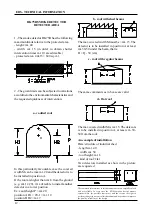
c) Observe the screen which is behind the lens
inside the transmitter(right lens) from the lateral
window. You will see a bright point representing
the lamp image. Adjust the transmitter's direction,
using the proper B screws and the key included,
so that the bright point lays right in the center, where
there's a small hole through which you can see the
photodiode. It’s important that the bright point falls
exacly in the center of the photosensitive element.
This area is represented by a small dark square at
the center of the photodiode (see fig.4). With this
procedure the device will be optically aligned with
the reflector.
5 - SETUP
5.1
- Power up the device. If the previous optical
alignement operations have been carefully carried
out, the following conditions must be found:
internal red LED light switched off
internal yellow LED light switched off
alarm relay R not powered or powered.
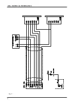
This depends on the position of the JP3 jump (see
fig. 8)
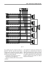
buzzer or LED connected to the OC output
terminal not powered (see fig. 9)
voltage at terminal TP1 (see 3.1) higher than 3 V
5.2
- Looking at the instrument's measure
(connected between TP1 and negative terminal)
adjust the V screws slowly to obtain the maximum
output signal. If this operation is not sufficient to
obtain a good output, it means that the optical
alignment with the reflector has been done
incorrectly.
5.3
- The transmitter emits a conic beam, whose
form and size related to the distance between the
transmitter and the reflector, are shown in the
figures 5 and 6. It is important that the reflector is
in the center of the beam emitted by the transmitter,
because in these conditions, even if some small
movements of the wall or surface on which the
device is assembled occur (caused by the strains),
the reflector always remains inside the beam. To
obtain this, the delicate truing operation with signal
measure as decribed in points 4.1and 5.2, must be
carried out with the greatest care. Attention: since
the device bases its working on the reflection of
the emitted beam, this reflection must be realized
only by the FX reflector, not by other elements.To
make sure that this result is obtained,
the reflector
must be obscured
by a not-reflecting panel. In this
case the instrument (connected between TP1 and
negative terminal) must indicate a voltage under 2
V (read further instructions).
5.4
- Adjust the sensitivity operating on P4 trimmer
and remembering what follows:
high sensitivity is obtained with signals between
3 and 5V (between TP1 and negative terminal)
medium sensitivity is obtained with 5-8 V
low sensitivity is obtained with 8 V or more
Remember that the adjusted signal is subjected to
a lowering of about 1 V when the device cover is
assembled, due to the frontal mask absorption.
Therefore the signal must be increased of about
1 V to be obtain a perfect adjustment.
5.5
- The sensitivity is to be adjusted according
to the environmental situation. Normally the level
is set for a medium sensitivity, but in case of dusty
environments (furniture factories, ecc) it is better
to use a lower sensitivity (8 V and over).
5.6
- The device is factory set to work with normally
not powered relays. If you wish to have the opposite
situation operate on the JP3 jump as follows:
pos. 1-2 normally powered relay
pos. 2-3 normally not powered relay
Remember that in pos. 2-3 the device
comsumption passes from 14 mA to 28 mA.
6 - WORKING TEST
6.1
- Verify the detector's working putting a not
reflecting panel
in front of reflector
. As soon as
the signal drops under the treshold level of
prealarm (3 V), the yellow LED must flash.

