4
EDS - TECHNICAL INFORMATION
If you let the signal drop under the alarm threshold
level (2 V), after a 6" delay the red LED must light
up and the alarm relay must be powered.
7 - SETTING THE DETECTOR FOR HIGH
SENSITIVITY
7.1
- You can let RK75R detector work at an even
higher sensitivity than the one given above (3-5
V). In this case it is necessary to act as follows:
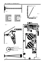
measure the voltage between the negative
terminal and the test point TP3, which is near
by prealarm led LD2 (see fig. 8), with a 10 V
full-scale high impedance voltmeter
the measured voltage will be 3V (factory adjusted)
adjust the P6 trimmer to obtain a voltage from
3 V to 2,2 - 2,5 V
adjust the P4 trimmer in such to obtain a 2,7-3
V between TP1 and negative terminal.
Anyway, be careful, because in such conditions even
a little drop of the signal is enough to generate an
alarm.If the environmental conditions are favourable,
the high stability of the detector circuits allows a very
good performance even in such limit conditions.
8 - SETTING THE DETECTOR FOR
SHORT DISTANCE
8.1
- If the RK75R detector works on a short
distance , in some cases the JP1 jumper must be
shifted to the pos. 2-3, to reduce the emitted beam
power and to get a good adjustment. In this case
we have a power reduction of about 50%.
Therefore we have:
pos. 2-3 power reduced of 50%
pos. 1-2 nominal power
In this operation don’t give satisfactory results it is besides
possible to do a fine adjustment using the P3 trimmer:
- counterclockwise the signal between TP1 and
negative terminal reduces gradually
- clockwise the signal increases
We suggest to do this adjustment only if stricly
needed.
9 - REMOTE DETECTOR CONTROL
9.1
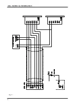
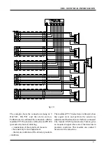
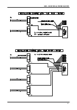
- The remote adjustment of the sensitivity can
be adequately done using the optional modules
EV570 (electronic voltmeter) and EV450
(piezoelectric buzzer), remote connected as shown
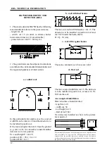
TECHNICAL DATA
Power supply: 12/24 Vcc (-10+20%)
Protection against inversion of polarity
Current: 10 mA with normally de-energized alarm relay, 25mA
with normally enegized alarm relay
sensitivity adjustment: with internal trimmer or remote (with the
accessory EV570)
red LED for the indication of alarm
red YELLOW for the indication of prealarm condition
output alarm realy: 1A/24 V cc
prealarm output: (Open Collector - transitor NPN) 50 mA output max
trimmer for the regulation of the prealarm trigger point
optical capacity
0-25 m. with reflector FX/01
0-20 m. with reflector FX/04
0-40 m. with reflector FX/02
0-30 m. with reflector FX/05
detected area: max 600 mq
protection class: IP50 (IEC 529-144)
dimensions: 162x62x63 mm
plastic box (base red or black a choise - cover black)
weight: 250 gr.
9 - REMOTE CONTROL
in the schematic of fig. 9
9.2
-
If you want to have the remote adjustment of
the sensitivity don’t forget to shift the inner JP2 iumper
from pos. 2-3 to pos. 1-2. In this way the internal P4
trimmer for the sensitivity adjustment, is turned off
and the output terminals TP2-TP3 for the connection
with the external trimmer assembled on the module
EV570 (see fig. 9) are switched on.
10 - MAINTENANCE
10.1
- the RK75R detector needs a simple and
periodic maintenance. It can be programmed or
made automatic with the suitable signal given from
the the detector.When the RK75R goes in prealarm
condition, it outputs the following prealarm signal
activating of the static output OC PRE-AL (OPEN
COLLECTOR). It's suggested to use this signal
because it gives a precise indication of the need
of maintenance.
10.2
- the maintenance operations are the
following:
cleaning of the plastic cover of detector. It is
suggested to use a cloth dampened with water
and some little drops of soap. Never use alco-
ol, ammonia and others similar products.
control an tight the internal terminals block.
control the optical aligment between the trasmitter
and receiver if the surface or the wall on which
they are mounted, is subject to deformation.

